
Getting started with the HC-06 Bluetooth module

Adding wireless communication to an Arduino project usually starts with a Bluetooth serial module, and the HC-06 is one of the most common choices. It's cheap, widely available, and does one job well: it lets a phone or computer connect to your board and exchange data as if the two were joined by a cable. Four pins, one operating mode, and a small set of configuration commands is the whole picture. That simplicity comes with a real constraint though, and knowing it upfront saves time later, since the HC-06 only accepts incoming connections and can't reach out to another device on its own.
This article covers the module from the ground up: what it can and can't do, how to wire it safely, how to configure it, and how to build something with it. Along the way it points out where the HC-06 differs from the HC-05, since the two are frequently confused and picking the wrong one can cost you a rebuild.
Components
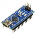
| 1x Arduino Nano (or another Arduino module)
|
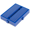
| 1x Mini-breadboard
|
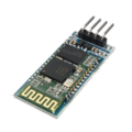
| 1x HC-06 Bluetooth Module
|
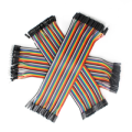
| Dupont wires
|
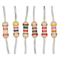
| Resistors kit
|
What is the HC-06
The HC-06 is a Bluetooth Serial Port Profile (SPP) module built on the BC417 chipset. It communicates with the Arduino over a standard UART serial link, and once a device connects, it runs in transparent mode. Anything the Arduino writes to the module goes out over Bluetooth to the connected phone or computer, and anything that device sends back arrives at the Arduino's serial pins as if it had been typed into a terminal. The module doesn't parse, buffer, or modify the data. It's a wireless replacement for a serial cable. This is what makes the HC-06 straightforward to program against. There's no Bluetooth library to install, no pairing logic in your sketch, and no message framing to implement. If your code already knows how to use Serial.print() and Serial.read(), it already knows how to use the HC-06.
Where things get interesting is how the connection itself gets established, because this is where the HC-06 and the HC-05 genuinely diverge. The HC-06 has exactly one connection behavior. It powers up, starts advertising, and stays discoverable until something connects to it. There is no state to check, no role to configure, and no way to leave it in a condition where it silently refuses connections. Plug it in and it's ready.
So the HC-06 isn't more capable, and framing it that way would be wrong. It's more predictable. When the Arduino is the peripheral and something else drives the connection, that predictability is worth more than flexibility you aren't going to use. The failure modes that eat the most debugging time on an HC-05 simply don't exist here.
Key specs worth knowing before you start:
Bluetooth version: 2.0 + EDR
Default baud rate: 9600
Operating voltage: 3.3V logic (most breakout boards accept 3.6V to 6V)
Default pairing PIN: 1234
Default device name: HC-06
Role: slave only, not configurable
Comparing HC-06 vs HC-05
Slave-only sounds like a limitation, and in one specific case it is a hard one. Two HC-06 modules cannot talk to each other. Both sit there advertising, neither reaches out, and nothing happens. Any project involving two Arduino boards communicating wirelessly needs at least one HC-05 configured as master, or a different technology entirely.
Everything else falls comfortably inside the HC-06's range. A phone controlling a robot, a laptop pulling sensor readings, a tablet driving a display, all of these have a host device that initiates the connection. The Arduino is the peripheral, which is exactly the role the HC-06 was built for.
The tradeoff runs in the other direction too. The HC-06 has no AT command mode to enter, no EN pin to pull HIGH, and no button to hold during power up. Configuration commands work whenever no device is connected, at the module's normal baud rate. This removes an entire category of setup problems, the ones where a module refuses to respond because it silently booted into the wrong mode.
A quick summary of the practical differences:
HC-06 | HC-05 | |
|---|---|---|
Role | Slave only | Master or slave |
Pins | 4 | 6 |
AT mode | Always available when disconnected | Requires EN pin or button at power up |
AT baud rate | Same as configured rate | Always 38400 |
Command syntax |
|
|
Line ending | None | Both NL and CR |
Board to board comms | Not possible | Possible |
The HC-06 is the right call when the requirements are known and the Arduino is clearly the peripheral. The HC-05 earns its extra complexity when the project might grow into something that needs master mode.
HC-06 board pinout
The breakout board exposes four pins, which is all the module needs.
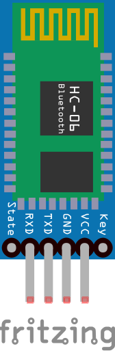
VCC and GND are the power pins. On a breakout board with an onboard voltage regulator, VCC accepts 5V directly from the Arduino. GND connects to Arduino GND as usual.
TXD and RXD are the serial communication pins. TXD is the module's transmit line and connects to the Arduino's RX pin. RXD is the module's receive line and connects to the Arduino's TX pin. The RXD line requires a voltage divider for safe operation, which is covered in the wiring section.
There is no STATE pin and no EN pin on a standard HC-06 board. If you need to detect connection status in software on this module, the usual approach is a keepalive character sent from the host at a regular interval, with the Arduino treating a timeout as a disconnect.
Wiring schema with Arduino
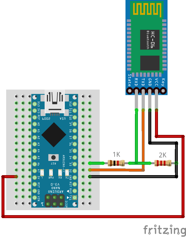
Connect VCC to the Arduino's 5V pin and GND to GND. For the serial lines, HC-06 TXD goes to Arduino RX and HC-06 RXD goes to Arduino TX, crossed so that each side's transmit reaches the other side's receive.
The TXD output sits at 3.3V, which a 5V Arduino reads correctly as HIGH with no extra circuitry. The RXD input is the pin that needs protection. It's 3.3V logic, and driving it with the Arduino's 5V TX line stresses the input over time even though it often appears to work at first. A voltage divider on that line brings the signal down to a safe level.
The voltage divider uses a 1kΩ resistor between Arduino TX and HC-06 RXD, and a 2kΩ resistor between HC-06 RXD and GND. The output voltage is calculated with the standard voltage divider formula:
Vout = Vin × R2 / (R1 + R2)
Where R1 is the resistor between the input and the output node, and R2 is the resistor between the output node and GND. Plugging in the values:
Vout = 5V × 2000 / (1000 + 2000) = 5V × 0.667 = 3.33V
That lands safely inside the module's input range. Any resistor pair holding the same 1:2 ratio works, so 2kΩ and 4kΩ or 10kΩ and 20kΩ are equally valid. The 1kΩ and 2kΩ combination is simply the easiest to find in a standard resistor kit.
 If you're working with an Arduino Mega, you have additional hardware serial ports available (
Serial1, Serial2, Serial3), so SoftwareSerial isn't necessary. Wire TXD and RXD to the appropriate hardware serial pins and use the corresponding Serial object in your code. The voltage divider on RXD still applies regardless of which Arduino you use.
Always disconnect the HC-06's RXD line before uploading a sketch. Even when using SoftwareSerial, the module can interfere with the upload process on some configurations, and disconnecting takes only a couple of seconds.
Configuring the module with AT commands
The HC-06 listens for AT commands under one condition: no Bluetooth device is currently connected. That's the entire rule. Power it up unpaired and it accepts configuration at its normal baud rate. Let a phone connect and it goes transparent, passing everything through untouched. There's no mode to enter and no way to get stuck in the wrong one.
Upload this passthrough sketch to bridge the Serial Monitor to the module:
#include <SoftwareSerial.h>

// Use pins 2 and 3 as RX and TX for the HC-05
SoftwareSerial BTSerial(2, 3);

void setup()
{
  // Match the AT mode baud rate in the Serial Monitor
  Serial.begin(9600);

  // HC-06 communication, must match the module's configured baud rate
  BTSerial.begin(9600);

  Serial.println("Ready. Type AT commands below.");
}

void loop()
{
  // Forward anything received from the HC-05 to the Serial Monitor
  if (BTSerial.available()) {
    Serial.write(BTSerial.read());
  }

  // Forward anything typed in the Serial Monitor to the HC-05
  if (Serial.available()) {
    BTSerial.write(Serial.read());
  }
}
Once uploaded, open the Serial Monitor (Tools > Serial Monitor, or Ctrl+Shift+M), set the baud rate to 9600, and set the line ending to "No line ending". This last setting trips people up regularly, because the HC-06 expects raw commands with nothing appended. Sending a trailing newline can cause the module to reject the command silently.
Type AT and hit Send. The module replies with OK, confirming the serial link is healthy. From there, send configuration commands one at a time:
The most useful configuration commands are:
Command | What it does | Example response |
|---|---|---|
| Test connection |
|
| Set device name |
|
| Set pairing PIN |
|
| Set baud rate |
|
| Get firmware version |
|
Note the syntax: the value follows the command with no separator character. To rename the module and change its PIN:
AT+NAMEHiBit
AT+PIN5678
Both take effect immediately, though a new device name only becomes visible to other devices after a power cycle. Baud rate changes apply instantly, which means the passthrough sketch goes silent until BTSerial.begin() is updated to match. The AT+BAUD command takes a single digit code rather than the rate itself:
Baud rate | AT command |
|---|---|
1 | 1200 |
2 | 2400 |
3 | 4800 |
4 | 9600 (default) |
5 | 19200 |
6 | 38400 |
7 | 57600 |
8 | 115200 |
Above 57600, SoftwareSerial starts dropping characters under load. If a project genuinely needs that throughput, move to a board with a spare hardware UART rather than pushing the library past what it handles reliably.
Changing the PIN from the default is worth doing on anything that leaves the workbench. The HC-06 has no encryption beyond Bluetooth 2.0 pairing, and 1234 is the first thing anyone tries.
Connecting to a Bluetooth serial device on Linux
A phone is the most common way to talk to an HC-06, but a Linux machine works just as well and is often more convenient during development. The module uses the Serial Port Profile (SPP), so the connection flow differs from pairing a headset or keyboard. Instead of the desktop Bluetooth applet handling everything, you pair the device and then bind it to a virtual serial port yourself.
Start by finding the module's Bluetooth address. Unlike some SPP modules, the HC-06 has no reliable AT command for querying its own address, so scanning is the practical approach:
bluetoothctl
agent on
default-agent
scan on
Wait for the module to appear in the output. It shows up under whatever name you configured, or HC-06 by default, alongside its address in the form XX:XX:XX:XX:XX:XX. Once you see it, pair and trust the device:
pair <ADDRESS>
trust <ADDRESS>
scan off
exit
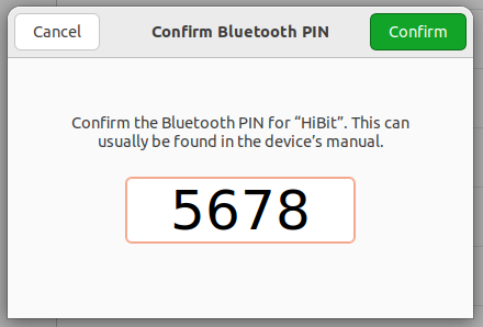
The pair step prompts for the PIN, which is 1234 unless you changed it with AT+PIN. The agent on and default-agent commands run earlier are what make that prompt appear, and skipping them is a common reason pairing fails without an obvious error. Marking the device as trusted means future connections won't ask again.
 With the module paired, bind it to a virtual serial port using
 rfcomm:
sudo rfcomm connect /dev/rfcomm0 <ADDRESS>
This terminal needs to stay open, since closing it tears down the connection. The command creates a device node at /dev/rfcomm0 that behaves like any other serial port.
In a second terminal, open the port at the module's configured baud rate:
# Interactive session (default baud rate for HC-05/HC-06 is 9600)
screen /dev/rfcomm0 9600

# Or send a string directly
echo "hello" > /dev/rfcomm0
This makes Linux a useful testing environment: shell scripts can drive the Arduino, output can be piped into a file for logging, and the whole setup integrates with tooling you already have.
A practical example with remote LED control
With the module wired and configured, here's a working example covering the full loop. A phone sends a command over Bluetooth, the Arduino acts on it, then reports back to both the phone and the Serial Monitor.
Wire up an LED with a 220 ohm resistor to pin 13: anode through the resistor to the pin, cathode to GND.
#include <SoftwareSerial.h>

SoftwareSerial BTSerial(2, 3); // RX, TX

const int ledPin = 13;
char command; // Stores the single character received from the phone

void setup()
{
  pinMode(ledPin, OUTPUT);

  // For monitoring activity in the Serial Monitor
  Serial.begin(9600);

  // For communicating with the HC-06
  BTSerial.begin(9600);

  Serial.println("Bluetooth LED control ready.");
}

void loop()
{
  if (BTSerial.available()) {
    command = BTSerial.read();

    // Echo the received character to the Serial Monitor for debugging
    Serial.print("Received: ");
    Serial.println(command);

    if (command == '1') {
      digitalWrite(ledPin, HIGH);
      BTSerial.println("LED ON"); // Confirm back to the phone
      Serial.println("LED ON");   // Also log it locally
    }

    if (command == '0') {
      digitalWrite(ledPin, LOW);
      BTSerial.println("LED OFF");
      Serial.println("LED OFF");
    }
  }
}
Sending confirmations to both destinations is worth the two extra lines. The phone needs feedback so the user knows the command landed, and the Serial Monitor gives you a wired view of what the module is actually delivering when the wireless side misbehaves.
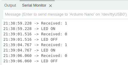 Pair the HC-06 from your phone's Bluetooth settings. It'll appear under the name you configured, or HC-06 by default. Enter the PIN when prompted (default: 1234). Once paired, install a Bluetooth terminal app.
Open the app, connect to the module, and send 1 to turn the LED on and 0 to turn it off. The module forwards your input straight to the Arduino's serial buffer, the Arduino reads it and responds, and that response travels back to your phone. You can watch both sides of the conversation in the Serial Monitor at the same time.
Working with structured commands
Single-character commands work fine for simple on/off control, but real projects usually need to pass values, not just triggers. A clean way to handle this is to define a minimal text protocol: each command is a short string with a prefix that identifies what it controls, followed by a colon and the value, terminated by a newline. For example, B:128 means set brightness to 128.
On the Arduino side, you read incoming characters one by one and accumulate them in a string until you hit the newline. At that point you have a complete command, you parse it, act on it, and clear the buffer for the next one. Here's that pattern applied to PWM brightness control on pin 9:
#include <SoftwareSerial.h>

SoftwareSerial BTSerial(2, 3); // RX, TX

const int pwmPin = 9;
String inputBuffer = ""; // Accumulates incoming characters until a full command arrives

void setup()
{
  pinMode(pwmPin, OUTPUT);

  // For monitoring activity in the Serial Monitor
  Serial.begin(9600);

  // For communicating with the HC-06
  BTSerial.begin(9600);

  Serial.println("Bluetooth LED control ready.");
}

void loop()
{
  while (BTSerial.available()) {
    char c = BTSerial.read();

    if (c == '\\n') {
      // Newline signals the end of a command, process what we've collected
      processCommand(inputBuffer);

      // Clear the buffer ready for the next command
      inputBuffer = "";
    } else {
      // Keep appending characters until the newline arrives
      inputBuffer += c;
    }
  }
}

void processCommand(String cmd)
{
  cmd.trim(); // Strip any stray whitespace or carriage returns

  if (cmd.startsWith("B:")) {
    // Extract the number after "B:" and convert it to an integer
    int value = cmd.substring(2).toInt();

    // constrain() clamps the value to the valid PWM range 0-255
    value = constrain(value, 0, 255);

    analogWrite(pwmPin, value);

    BTSerial.print("Brightness set to: ");
    BTSerial.println(value); // Confirm back to the phone

    Serial.print("Brightness set to: ");
    Serial.println(value);   // Also log it locally
  } else {
    BTSerial.println("Unknown command. Try B:0 to B:255");
    Serial.println("Unknown command received");
  }
}
Configure the terminal app to append a newline (\\n) to each message (usually found in the app's settings), then send B:128 for half brightness, B:255 for full, or B:0 for off. Keeping processCommand separate from loop pays off as the protocol grows. Adding S: for a servo angle or R: for an RGB value means adding one more if block, with no changes to the reading logic at all.
Testing your setup
Work through this in order, since each step depends on the one before it.
Start with power. A powered HC-06 waiting for a connection blinks rapidly, roughly twice per second. A dark LED points at VCC or GND before anything else. If the module has power but the blink pattern looks wrong, check that nothing is already paired to it.
Next, verify the serial link with the passthrough sketch. With nothing paired, send AT and expect OK. Garbled characters mean the baud rate in the sketch doesn't match the module. Complete silence usually means RX and TX are crossed the wrong way, or a phone is already connected and the module has gone transparent, which is easy to miss because the module gives no indication in the Serial Monitor.
With AT commands responding, pair from the phone and watch the LED shift to a solid or slower pattern. Then load the LED control sketch and send a few commands, keeping the Serial Monitor open. Every received character should print there. If the phone shows a connection but nothing appears in the monitor, the Bluetooth link is fine and the problem sits between the module and the Arduino.
To take the Arduino out of the picture completely, short the module's TXD and RXD pins together and connect it to a USB-to-serial adapter. Everything you type gets echoed straight back. A clean loopback confirms the module itself is working, which narrows the search to wiring or sketch logic.
The most common problems and their causes:
No response to AT commands: a device is already connected, or the sketch and module disagree on baud rate.
Garbled characters: baud rate mismatch between
BTSerial.begin()and the module's configured rate.Commands rejected despite a good connection: line ending set to something other than "No line ending" in the Serial Monitor.
Module missing from the Bluetooth scan: it may still be connected to another device. Some units stop advertising once paired, so power cycle it.
Dropped or delayed data:
SoftwareSerialrunning out of headroom. Drop back to 9600 or move to a hardware UART.
Conclusions
Choosing the HC-06 means accepting one hard limit in exchange for a smaller surface area of things that can go wrong. It won't reach out to another device, and no amount of configuration will change that. In return, there's no mode to enter, no timing window to hit during power up, and no second baud rate to remember. For the common case where a phone or computer drives the connection and the Arduino responds, that trade is a good one. Get the voltage divider right, keep the baud rates in sync, and the module fades into the background where a good component belongs.
Credits
Official GitHub: https://github.com/hibit-dev/hc-06




0 Comments