Using the DS18B20 temperature sensor with Arduino Nano
The DS18B20 is a digital temperature sensor that comes in two versions: a small TO-92 package, and a waterproof variant often encased in a metal tube with a long cable. Both provide digital temperature readings and can be used in many indoor and outdoor projects. The DS18B20 uses a protocol called 1-Wire, which only needs one data line to communicate and can support multiple sensors on the same pin.
The sensor supports several resolution levels: 9, 10, 11, or 12 bits. The default is 12-bit resolution, which gives a precision of 0.0625°C. Lower resolutions can speed up readings, while higher ones provide more detailed temperature data. The DS18B20 sensor measures temperatures within a range of -55°C to +125°C (-67°F to +257°F).
Components
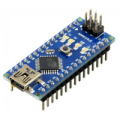
| 1x Arduino Nano (or another Arduino module)
|
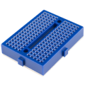
| 1x Mini-breadboard
|
| 1x DS18B20 module
|
| Resistors kit
|
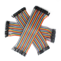
| Dupont wires
|


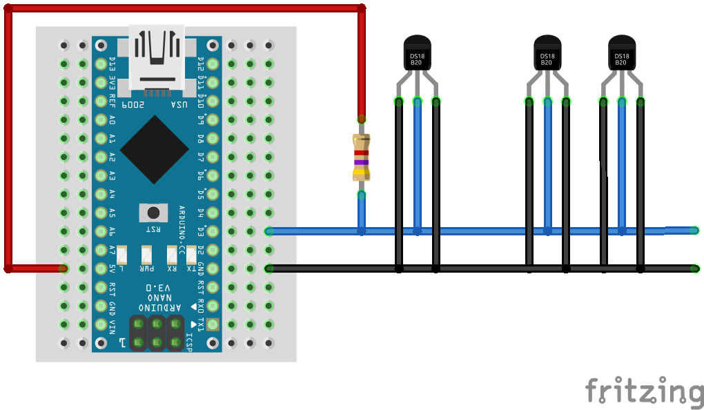
Wiring schema
The DS18B20 offers two power options. It can be powered by an external supply through its VDD pin, or it can draw power directly from the data line using a method called parasite mode, which eliminates the need for a separate power connection.
In both power modes, a pull-up resistor must be connected between the DQ (data) pin and VCC to ensure the data line stays in the proper state when idle. A 4.7kΩ resistor is commonly used for this purpose. For longer cables, such as with the waterproof version, you might need to adjust the resistor value, but 4.7kΩ typically works fine.
You can read temperatures from multiple DS18B20 sensors using a single digital pin on the Arduino. To do this, simply connect all the sensors' data pins together and link them to the same digital pin on the Arduino.
Standard mode
A 3-wire connection is required, with power supplied directly to the VDD pin. Below is the schematic to guide your wiring:
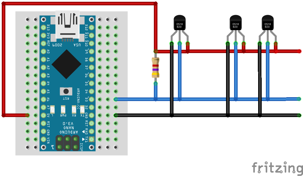
VDD → Arduino 5V
GND → Arduino GND
DQ → Arduino D3 (or any digital pin)
4.7kΩ resistor between DQ and VDD
Parasite mode
Only the data and ground wires are needed, as the sensor draws power directly from the data line. Here's the schematic to follow for this setup:
VDD → Arduino GND
GND → Arduino GND
DQ → Arduino D3 (or any digital pin)
4.7kΩ resistor between DQ and 5V
Install required Arduino libraries
Before uploading any code, you need to install two libraries that handle communication with the DS18B20 sensor: OneWire and DallasTemperature.
To install them:
Open the Arduino IDE.
Go to the Sketch menu and select Include Library > Manage Libraries…
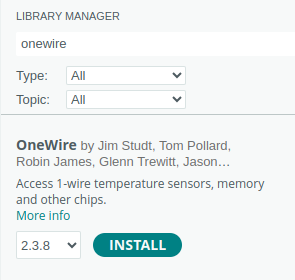
In the Library Manager, type OneWire into the search box. Find the library and click install.
![OneWire Arduino library installation]()
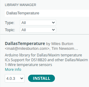
Next, search for DallasTemperature and install the library.
![DallasTemperature Arduino library installation]()
Once both are installed, you can include them in your sketch and start working with the sensor:
#include "OneWire.h"
#include "DallasTemperature.h"
These libraries take care of the communication protocol and make it easy to get temperature readings with just a few lines of code. Refer to the original DallasTemperature library file, which includes all the available functions necessary for managing temperature sensors.
Arduino code
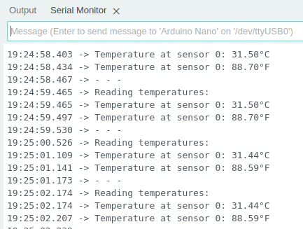
This example sets up the sensor on digital pin 3, starts communication, and reads temperature values once every second. The output shows both Celsius and Fahrenheit formats in the Serial Monitor.
#include "OneWire.h"
#include "DallasTemperature.h"

#define DS18B20_DATA_PIN 3

OneWire oneWire(DS18B20_DATA_PIN);
DallasTemperature sensors(&oneWire);

void setup()
{
  pinMode(DS18B20_DATA_PIN, INPUT);

  Serial.begin(115200);
  sensors.begin();
}

void loop()
{
  Serial.println("Reading temperatures:");
  sensors.requestTemperatures();

  Serial.print("Temperature at sensor 0: ");
  Serial.print(sensors.getTempCByIndex(0));
  Serial.print("\\xC2\\xB0"); //Print degree symbol
  Serial.println("C");

  Serial.print("Temperature at sensor 0: ");
  Serial.print(sensors.getTempFByIndex(0));
  Serial.print("\\xC2\\xB0"); //Print degree symbol
  Serial.println("F");

  Serial.println("- - -");

  delay(1000);
}
This example reads from the first sensor found on the data line. If you connect multiple sensors, you can address each by index or unique device ID.
Testing
Once the code is uploaded, the Serial Monitor in the Arduino IDE should be opened with the baud rate set to 115200. The temperature readings will appear in both Celsius and Fahrenheit, as shown in the next image.
Conclusion
The DS18B20 is often used in projects like home weather displays, greenhouse monitoring, aquariums, and smart heating systems. Its digital output makes it more resistant to electrical noise, especially over long wires. The waterproof version is especially useful when you need to place the sensor outdoors or in contact with liquids. If you're using multiple sensors or planning a longer wiring setup, make sure your resistor value and cable quality are appropriate. For most short-distance setups, though, the standard 4.7kΩ pull-up is fine.
Credits
Official GitHub: https://github.com/hibit-dev/ds18b20


0 Comments