Low power consumption mode in Arduino
Battery-powered Arduino projects have one common enemy: a board that drains power even when it has nothing to do. By default, Arduino runs at full speed continuously, burning through battery charge whether it's actively doing something or just waiting. Low power mode solves this by putting the microcontroller to sleep when it's idle, waking it up only when there's actual work to do. The concept is straightforward: the microcontroller spends most of its time asleep, wakes up to do something useful (take a sensor reading, send data, check a button), then goes back to sleep immediately.
Components
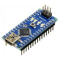
| 1x Arduino Nano (or another Arduino module)
|
Sleep modes
The ATmega328P (the chip on most Arduino boards) offers several sleep depths:
Idle
Stops the CPU but keeps peripherals like timers and UART running. Modest savings, fast wake-up.
Power-save
Shuts down most of the chip but keeps an internal timer running for scheduled wake-ups.
Power-down
The deepest mode. Almost everything stops and current drops to 1-2µA. The chip wakes only on an external interrupt or a watchdog timer timeout.
Power-down is what most battery projects use.
Watchdog timer
Before going further, it's worth understanding the watchdog timer, since it plays a central role in timed wake-ups. The watchdog timer (WDT) is a small, independent hardware timer built into the microcontroller. It runs on its own clock, separate from the main CPU, which means it keeps ticking even when the rest of the chip is asleep. Its original purpose is to reset the chip if the firmware crashes or hangs, but in low power applications it's used differently: configured to fire an interrupt at a set interval, it becomes the mechanism that wakes the chip up on a schedule. The maximum interval the ATmega328P watchdog supports is 8 seconds per cycle.
Install low power Arduino library
There are three main approaches to putting an Arduino to sleep, ranging from a raw hardware API to higher-level library wrappers. The right choice depends on how much control you need and how much boilerplate you're willing to manage.
AVR standard library
The
avr/sleep.handavr/power.hheaders are part of the AVR toolchain that ships with the Arduino IDE. They give you direct register-level control over every sleep mode and peripheral, with no external dependencies. The trade-off is verbosity: you need to configure sleep mode registers, manage the watchdog timer manually, and handle interrupt setup yourself. It's the right tool when you need precise control, but for most projects it's more work than necessary.ArduinoLowPower
This is the official library from Arduino. Despite its compatibility page listing AVR boards like the Uno, Nano, and Mega, it does not actually compile on AVR targets. In practice it only works on SAMD21 and nRF52 boards: the MKR family, the Nano 33 IoT, and the Zero. If you're on one of those boards, its API is clean and straightforward.
LowPower by Rocket Scream
It supports all major sleep modes and works reliably for AVR-based boards (Uno, Nano, Pro Mini, and most other ATmega chips). It wraps the low-level AVR sleep API into a single, readable function call, handles watchdog timer configuration automatically, and lets you control peripheral state as part of the same call.
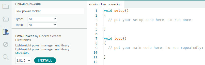
For ATmega-based projects, LowPower is the practical default. To install it, open the Arduino IDE, go to Sketch > Include Library > Manage Libraries, search for "Low-Power", and install the one by Rocket Scream Electronics.
 Once installed, you include it in your sketch with:
#include "LowPower.h"
This gives you access to the LowPower object and all its methods.
The power down method
The library exposes a powerDown() method that handles everything in a single call: selecting the sleep mode, configuring the watchdog timer, and managing peripheral state.
Its signature is:
LowPower.powerDown(period, adc, bod);
And, it takes three arguments:
periodsets how long the chip sleeps before the watchdog timer wakes it up automatically. The available values are:Value
Sleep duration
SLEEP_15MS15 milliseconds
SLEEP_30MS30 milliseconds
SLEEP_60MS60 milliseconds
SLEEP_120MS120 milliseconds
SLEEP_250MS250 milliseconds
SLEEP_500MS500 milliseconds
SLEEP_1S1 second
SLEEP_2S2 seconds
SLEEP_4S4 seconds
SLEEP_8S8 seconds
SLEEP_FOREVERIndefinite, no watchdog timer configured
SLEEP_FOREVERis a special case. The watchdog timer is not activated at all, so the chip stays asleep until an external interrupt wakes it. If you use this value with no interrupt attached, the chip will sleep indefinitely with no way to wake up programmatically.adccontrols the analog-to-digital converter (ADC) during sleep. The ADC is the hardware block responsible for reading analog pins (analogRead()). Even when your code isn't actively taking readings, the ADC circuit stays powered unless you explicitly turn it off. It draws around 0.3mA on its own, which is significant when your entire sleep target is in the low microamp range.Pass
ADC_OFFto shut it down for the duration of sleep. The library automatically restores it when the chip wakes up, soanalogRead()works normally afterwards with no extra steps needed on your part.Pass
ADC_ONto leave it running, which is only necessary if your wake-up ISR needs to take an analog reading before the main loop resumes. In practice,ADC_OFFis almost always the right choice.
bodcontrols the brown-out detector (BOD) during sleep. The BOD is a monitoring circuit that continuously watches the supply voltage and triggers a reset if it drops below a safe threshold (typically 2.7V on a 3.3V board, or 4.3V on a 5V board). Its purpose is to prevent the chip from operating in an undefined state when the battery is running low or the supply is unstable.Keeping the BOD active during sleep costs around 20-25µA continuously, which is a significant overhead when power-down mode can otherwise get the chip down to 1-2µA. Passing
BOD_OFFdisables it for the sleep period and recovers most of that overhead. The library re-enables it on wake-up.The trade-off is real though. With
BOD_OFF, if the supply voltage drops during sleep (a dying battery, a loose connection, inrush current from a sensor powering up), the chip can wake into a corrupted state with no reset to recover it. For stable, well-designed power supplies this is rarely a problem. For projects running off old or small batteries, or where the load changes dramatically between sleep and active phases, leavingBOD_ONis the safer option. For most typical battery projects with a reasonably fresh battery and stable circuit,BOD_OFFis fine.
Sleeping on a schedule
The most common pattern is waking up periodically to take a reading or perform a task. The watchdog timer handles this, firing an interrupt at a fixed interval to bring the chip out of sleep.
#include "LowPower.h"

void setup()
{
  Serial.begin(115200);
}

void loop()
{
  Serial.println("Taking a reading...");

  // Wait for Serial to finish transmitting before sleeping.
  // If you skip this, the output gets cut off mid-transmission.
  Serial.flush();

  // Sleep for 8 seconds, then wake up automatically via the watchdog timer.
  LowPower.powerDown(SLEEP_8S, ADC_OFF, BOD_OFF);

  // Execution resumes here after waking up. The loop repeats.
}
The watchdog timer maxes out at 8 seconds per interval. For longer sleep periods, chain multiple calls:
// Sleep for roughly 1 minute by chaining 8-second sleeps.
// Each call blocks until the watchdog fires, then moves to the next.
for (int i = 0; i < 7; i++) {
  LowPower.powerDown(SLEEP_8S, ADC_OFF, BOD_OFF);
}

LowPower.powerDown(SLEEP_4S, ADC_OFF, BOD_OFF);
Each call to powerDown blocks until the watchdog fires, then execution moves to the next call. Chaining them this way produces a cumulative sleep of any duration in 8-second increments, with a smaller final step to hit the exact target.
Waking up on an event
Some projects don't work on a fixed schedule. A door sensor, a button, or a motion detector needs to wake the device in response to something happening. For that, you use an external interrupt on pin 2 or pin 3, the only interrupt-capable pins on the Uno and most ATmega boards.
#include "LowPower.h"

const int wakePin = 2;

void setup()
{
  Serial.begin(115200);
}

void wakeUp()
{
  // This ISR (Interrupt Service Routine) runs when the interrupt fires.
  // It doesn't need to do anything; its only job is to wake the chip.
}

void loop()
{
  // Attach the interrupt before sleeping so the chip has something to wake up on.
  // digitalPinToInterrupt(wakePin) converts the pin number to its interrupt number.
  // LOW means the interrupt fires while pin 2 is held LOW, not just on the falling edge.
  attachInterrupt(digitalPinToInterrupt(wakePin), wakeUp, LOW);

  // Sleep indefinitely. The chip stays here until pin 2 is pulled LOW.
  LowPower.powerDown(SLEEP_FOREVER, ADC_OFF, BOD_OFF);

  // Detach immediately after waking to prevent spurious re-triggers
  // while the rest of the loop runs.
  detachInterrupt(digitalPinToInterrupt(wakePin));

  Serial.println("Woken by interrupt!");
  Serial.flush();
}
The interrupt is attached just before sleeping and detached immediately after waking, which keeps behaviour predictable and avoids spurious re-triggers during the work phase. On ATmega boards in power-down mode, only LOW and CHANGE are guaranteed to work as wake sources; RISING and FALLING may not reliably wake the chip from the deepest sleep.
Pros and cons
Low power mode is not entirely free. Here's what you gain and what you give up.
Pros:
Battery life improvements of 10x to 100x are realistic in practice.
No extra hardware required for basic sleep functionality.
Forces cleaner, more event-driven firmware structure.
Cons:
Serial output is lost during sleep. Always call
Serial.flush()before sleeping, or data in the buffer gets cut off mid-transmission.The watchdog timer drifts slightly with temperature and voltage, so it's not suitable for precise timekeeping over long periods.
Debugging gets harder since the chip isn't running during sleep. Print-based debugging requires careful placement of
Serial.flush()calls.On standard Uno boards, the USB chip and power LED keep drawing current even when the MCU is asleep, limiting real-world savings. The Arduino Pro Mini (especially the 3.3V version) is a much better fit for battery projects.
Conclusion
Low power mode is one of the more practical tools in embedded development. The core idea is simple, the library support is solid, and the impact on battery life is significant. A bit of extra care around Serial flushing and wake-up logic is all it takes to turn a power-hungry board into something that runs for months unattended.
Credits
Low Power library: https://docs.arduino.cc/libraries/low-power


0 Comments