Getting started with the HC-05 Bluetooth module
The HC-05 is one of the most popular Bluetooth modules in the Arduino ecosystem, and for good reason. It's affordable, well documented, and flexible enough to handle a wide range of use cases. It can operate as both a master and a slave device, meaning it can initiate connections to other Bluetooth devices as well as wait for them. For projects where you just need a phone to talk to an Arduino, that distinction doesn't matter much. But for anything more involved, like two Arduino boards communicating wirelessly, the HC-05 is the right tool for the job.
This article covers everything you need to get the HC-05 running with an Arduino: the pinout, how to wire it up safely, how to configure it through AT commands, and how to use it in a practical example.
Components
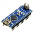
| 1x Arduino Nano (or another Arduino module)
|
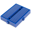
| 1x Mini-breadboard
|
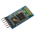
| 1x HC-05 Bluetooth Module
|
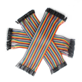
| Dupont wires
|
| Resistors kit
|

What is the HC-05
The HC-05 is a Bluetooth Serial Port Profile (SPP) module based on the BC417 chipset. It communicates with your Arduino over a standard UART serial link, so from the code's perspective, sending data over Bluetooth looks exactly like writing to Serial. There's no Bluetooth-specific library to learn and no packet framing to deal with. Bytes go in one side and come out the other wirelessly.
What sets the HC-05 apart is its ability to switch between master and slave roles. In slave mode it waits for another device to connect to it. In master mode it actively scans for and connects to another Bluetooth device, which is what makes Arduino-to-Arduino communication possible. The role is configurable through AT commands, so the same physical module can serve either purpose depending on what the project needs.
Key specs worth knowing before you start:
Default baud rate: 9600 (38400 in AT mode)
Operating voltage: 3.3V logic (most breakout boards accept 3.6V to 6V)
Default pairing PIN: 1234
Default device name: HC-05
HC-05 board pinout
The HC-05 breakout board exposes six pins. Two of them handle power, two handle serial communication, and the remaining two are available for more advanced control.
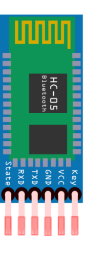
VCC and GND are the power pins. On a standard breakout board with an onboard voltage regulator, VCC accepts 5V directly from the Arduino. GND connects to Arduino GND as usual.
TXD and RXD are the serial communication pins. TXD is the module's transmit line and connects to the Arduino's RX pin. RXD is the module's receive line and connects to the Arduino's TX pin. The RXD line requires a voltage divider for safe operation, which is covered in the wiring section.
STATE is an output pin that reflects the current connection status of the module. It goes HIGH when a Bluetooth connection is active and LOW when the module is idle or pairing. You can connect it to a digital input pin on the Arduino and read it in your sketch to know at any point whether a device is currently connected, which can be useful for triggering behavior on connect or disconnect without relying on the data stream.
EN (sometimes labeled KEY on certain breakout boards) is the enable pin used to switch the module into AT command mode. Pulling it HIGH while the module powers up puts it into AT mode, where it accepts configuration commands at 38400 baud. When left floating or pulled LOW during power up, the module starts in normal communication mode at its configured baud rate. On breakout boards with a dedicated button, pressing that button while powering up does the same thing as pulling EN HIGH manually.
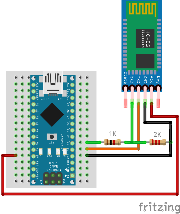
Wiring schema with Arduino
Connect VCC to the Arduino's 5V pin and GND to GND. For the serial lines, HC-05 TXD goes to Arduino RX and HC-05 RXD goes to Arduino TX, crossed so that each side's transmit reaches the other side's receive.
The TXD line coming out of the HC-05 outputs 3.3V, which a 5V Arduino reads correctly as HIGH without any additional circuitry. The RXD line going into the module is 3.3V logic only, so feeding 5V from the Arduino's TX pin directly into it can stress and eventually damage the module. A voltage divider on that line brings the signal down to a safe level.
The voltage divider uses a 1kΩ resistor between Arduino TX and HC-05 RXD, and a 2kΩ resistor between HC-05 RXD and GND. The output voltage is calculated with the standard voltage divider formula:
Vout = Vin × R2 / (R1 + R2)
Where R1 is the resistor between the input and the output node, and R2 is the resistor between the output node and GND. Plugging in the values:
Vout = 5V × 2000 / (1000 + 2000) = 5V × 0.667 = 3.33V
That 3.33V sits comfortably within the HC-05's safe input range. Other resistor combinations work too as long as the ratio stays the same, for example 2kΩ and 4kΩ, but 1kΩ and 2kΩ are the most commonly available values and work well in practice.
 If you're working with an Arduino Mega, you have additional hardware serial ports available (
Serial1, Serial2, Serial3), so SoftwareSerial isn't necessary. Wire TXD and RXD to the appropriate hardware serial pins and use the corresponding Serial object in your code. The voltage divider on RXD still applies regardless of which Arduino you use.
Always disconnect the HC-05's RXD line before uploading a sketch. Even when using SoftwareSerial, the module can interfere with the upload process on some configurations, and disconnecting takes only a couple of seconds.
Configuring the module with AT commands
The HC-05 has a dedicated AT command mode for configuration. To enter it, hold the button on the breakout board (or pull the EN pin HIGH) while connecting power to the module. The LED will blink slowly, roughly once every two seconds, confirming that AT mode is active. In this mode the module communicates at 38400 baud regardless of what baud rate it's configured to use in normal operation.
To send AT commands through the Arduino, upload this passthrough sketch. Note the 38400 in BTSerial.begin(), which is required for AT mode:
#include <SoftwareSerial.h>

// Use pins 2 and 3 as RX and TX for the HC-05
SoftwareSerial BTSerial(2, 3);

void setup()
{
  // Match the AT mode baud rate in the Serial Monitor
  Serial.begin(38400);

  // HC-05 AT mode always runs at 38400
  BTSerial.begin(38400);

  Serial.println("Ready. Type AT commands below.");
}

void loop()
{
  // Forward anything received from the HC-05 to the Serial Monitor
  if (BTSerial.available()) {
    Serial.write(BTSerial.read());
  }

  // Forward anything typed in the Serial Monitor to the HC-05
  if (Serial.available()) {
    BTSerial.write(Serial.read());
  }
}
Once uploaded, open the Serial Monitor (Tools > Serial Monitor, or Ctrl+Shift+M), set the baud rate to 38400, and set the line ending to Both NL & CR. The HC-05 requires the newline and carriage return characters at the end of each AT command to process it correctly.
Type AT and hit Send. The module should respond with OK. From there you can send configuration commands one at a time.
The most useful configuration commands are:
Command | What it does | Example response |
|---|---|---|
| Test connection |
|
| Set device name |
|
| Set pairing PIN |
|
| Set baud rate |
|
| Set slave mode |
|
| Set master mode |
|
| Get firmware version |
|
| Get module MAC address |
|
Note the syntax: the HC-05 uses = between the command and the value, and query commands end with ?. To rename the module, change the PIN, and confirm it's in slave mode, send these commands one at a time:
AT+NAME=HiBit
AT+PSWD=5678
AT+ROLE=0
For baud rate configuration, the AT+UART command takes three parameters: baud rate, stop bits, and parity. For standard use, stop bits and parity are always 0. Here's the full table of supported baud rates:
Baud rate | AT command |
|---|---|
1200 |
|
2400 |
|
4800 |
|
9600 |
|
19200 |
|
38400 |
|
57600 |
|
115200 |
|
After changing the baud rate, remember to update BTSerial.begin() in your sketches to match. There's rarely a reason to go above 57600 when using SoftwareSerial, as the library becomes unreliable at higher speeds. If your application genuinely needs more throughput, switch to a board with hardware serial ports rather than pushing SoftwareSerial beyond its limits.
Connecting to a Bluetooth serial device on Linux
Modules like the HC-05 and HC-06 use the Serial Port Profile (SPP), so the connection flow is slightly different from pairing a headset or keyboard. If you don't know the device's Bluetooth address, you can retrieve it via AT commands while the module is in AT mode:
AT+ADDR?
The response will look like:
+ADDR:98:D3:31:F9:F7:E2
Alternatively, scan for nearby devices:
bluetoothctl
scan on
Pair the device:
bluetoothctl
scan on
# wait for your device to appear, then:
pair <ADDRESS>
trust <ADDRESS>
scan off
exit
Use rfcomm to establish connection with SPP device:
sudo rfcomm connect /dev/rfcomm0 <ADDRESS>
Keep this terminal open. It creates a virtual serial port at /dev/rfcomm0.
In a second terminal:
# Interactive session (default baud rate for HC-05/HC-06 is 9600)
screen /dev/rfcomm0 9600

# Or send a string directly
echo "hello" > /dev/rfcomm0
Once /dev/rfcomm0 is up, it behaves like any serial port.
A practical example with remote LED control
With the module wired and configured, here's a complete working example. A smartphone sends a command over Bluetooth, the Arduino receives it and acts on it, then sends a confirmation back to the phone and to the Serial Monitor.
Wire up an LED with a 220 ohm resistor to pin 13: anode through the resistor to the pin, cathode to GND. Make sure the module is powered up normally without holding the button, so it starts in communication mode rather than AT mode.
#include <SoftwareSerial.h>

SoftwareSerial BTSerial(2, 3); // RX, TX

const int ledPin = 13;
char command; // Stores the single character received from the phone

void setup()
{
  pinMode(ledPin, OUTPUT);

  // For monitoring activity in the Serial Monitor
  Serial.begin(9600);

  // For communicating with the HC-05
  BTSerial.begin(9600);

  Serial.println("Bluetooth LED control ready.");
}

void loop()
{
  if (BTSerial.available()) {
    command = BTSerial.read();

    // Echo the received character to the Serial Monitor for debugging
    Serial.print("Received: ");
    Serial.println(command);

    if (command == '1') {
      digitalWrite(ledPin, HIGH);
      BTSerial.println("LED ON"); // Confirm back to the phone
      Serial.println("LED ON");   // Also log it locally
    }

    if (command == '0') {
      digitalWrite(ledPin, LOW);
      BTSerial.println("LED OFF");
      Serial.println("LED OFF");
    }
  }
}
Pair the HC-05 from your phone's Bluetooth settings. It'll appear under the name you configured, or HC-05 by default. Enter the PIN when prompted (default: 1234). Once paired, install a Bluetooth terminal app.
Open the app, connect to the module, and send 1 to turn the LED on and 0 to turn it off. The module forwards your input straight to the Arduino's serial buffer, the Arduino reads it and responds, and that response travels back to your phone. You can watch both sides of the conversation in the Serial Monitor at the same time.
Working with structured commands
Single-character commands work fine for simple on/off control, but real projects usually need to pass values, not just triggers. A clean way to handle this is to define a minimal text protocol: each command is a short string with a prefix that identifies what it controls, followed by a colon and the value, terminated by a newline. For example, B:128 means set brightness to 128.
On the Arduino side, you read incoming characters one by one and accumulate them in a string until you hit the newline. At that point you have a complete command, you parse it, act on it, and clear the buffer for the next one. Here's that pattern applied to PWM brightness control on pin 9:
#include <SoftwareSerial.h>

SoftwareSerial BTSerial(2, 3); // RX, TX

const int pwmPin = 9;
String inputBuffer = ""; // Accumulates incoming characters until a full command arrives

void setup()
{
  pinMode(pwmPin, OUTPUT);

  // For monitoring activity in the Serial Monitor
  Serial.begin(9600);

  // For communicating with the HC-05
  BTSerial.begin(9600);

  Serial.println("Bluetooth LED control ready.");
}

void loop()
{
  while (BTSerial.available()) {
    char c = BTSerial.read();

    if (c == '\\n') {
      // Newline signals the end of a command, process what we've collected
      processCommand(inputBuffer);

      // Clear the buffer ready for the next command
      inputBuffer = "";
    } else {
      // Keep appending characters until the newline arrives
      inputBuffer += c;
    }
  }
}

void processCommand(String cmd)
{
  cmd.trim(); // Strip any stray whitespace or carriage returns

  if (cmd.startsWith("B:")) {
    // Extract the number after "B:" and convert it to an integer
    int value = cmd.substring(2).toInt();

    // constrain() clamps the value to the valid PWM range 0-255
    value = constrain(value, 0, 255);

    analogWrite(pwmPin, value);

    BTSerial.print("Brightness set to: ");
    BTSerial.println(value); // Confirm back to the phone

    Serial.print("Brightness set to: ");
    Serial.println(value);   // Also log it locally
  } else {
    BTSerial.println("Unknown command. Try B:0 to B:255");
    Serial.println("Unknown command received");
  }
}
To test it, open your Bluetooth terminal app, make sure it's configured to append a newline (\\n) to each message (usually found in the app's settings), and send B:128 for 50% brightness, B:255 for full, or B:0 to turn it off. The processCommand function is intentionally separate from loop so that adding new command types later is just a matter of adding another if block with a different prefix. Adding S: for servo angle or R: for an RGB value follows exactly the same structure.
Testing your setup
Before integrating the HC-05 into a larger project, run through this checklist systematically. Start with the module itself: when powered up normally without holding the button, the LED should blink rapidly (roughly twice per second), indicating it's waiting for a connection. If the LED is blinking slowly instead, the module is in AT mode. Power cycle it without the button to return to normal operation.
Next, confirm AT command communication using the passthrough sketch from the configuration section. Enter AT mode, send AT in the Serial Monitor at 38400 baud, and expect OK back. If you get garbled characters, check that the Serial Monitor baud rate is set to 38400 and that the line ending is set to Both NL & CR. If you get nothing at all, the RX/TX lines are likely crossed the wrong way.
Once AT commands work, switch back to normal mode by power cycling without the button, pair from your phone, and confirm the LED on the module changes to a slower double-blink pattern indicating an active connection. Then run the LED control sketch and send a few commands. Watch the Serial Monitor in parallel: you should see each received character printed there, confirming the Arduino is reading the data correctly.
If you want to isolate the module's serial hardware from the Arduino entirely, short the module's TXD and RXD pins together and connect it to a USB-to-serial adapter. Whatever you type in a terminal gets echoed back immediately. If the loopback works, the module is fine and any remaining issue is in your wiring or sketch logic.
The most common problems and their causes:
No response to AT commands: module not in AT mode, wrong baud rate in Serial Monitor (must be 38400), or line ending not set to Both NL & CR.
Garbled characters: baud rate mismatch between
BTSerial.begin()and the module's configured rate, or Serial Monitor not set to 38400 in AT mode.Module not showing up in Bluetooth scan: it may already be connected to another device. Power cycle the module to force a disconnect.
Data drops or delays:
SoftwareSerialstruggling with throughput. Drop back to 9600, or switch to a hardware serial port on a board that has one.
Conclusions
The HC-05 is a solid, flexible choice for adding Bluetooth to any Arduino project. The wiring is simple, the AT command interface is straightforward once you know the baud rate and line ending requirements, and the transparent serial behavior means your existing code needs no changes to work over the air. Master mode adds room to grow if the project ever calls for device-to-device communication, and the STATE pin gives you a clean way to react to connection events without any polling logic. For most Arduino Bluetooth projects, it covers everything you'll need.
Credits
Official GitHub: https://github.com/hibit-dev/hc-05


0 Comments