How to use the AD Keyboard module with Arduino
When working on simple Arduino projects that need basic navigation or input, the AD keyboard module is a handy little tool. It's a 5-button unit that behaves like a directional pad, with four arrow-style buttons and one additional button. It doesn't require any soldering or setup, which makes it a practical choice for prototyping or small projects. You can plug it in and start using it right away, thanks to its three-pin layout and built-in resistors.
Components
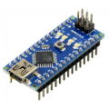
| 1x Arduino Nano (or another Arduino module)
|
| 1x Mini-breadboard $2.33 |
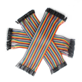
| Dupont wires
|

Wiring schema
The AD keyboard module has three pins: GND, VCC, and OUT. Here's how to connect them:
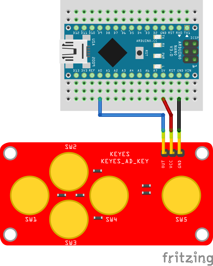
Connect the GND pin of the module to the GND on the Arduino.
Connect the VCC pin to the 5V pin on the Arduino. This powers the module.
Connect the OUT pin to A0, which is one of Arduino's analog input pins.
This module has five buttons: Up, Down, Left, Right, and a Select button. Instead of each button having a separate pin, all five share a single analog output pin. The trick is that each button is wired to a different resistor, so when you press a button, it sends a different voltage to the analog pin. Once everything is connected, you can upload a sketch to read the values and figure out what button is being pressed.
Arduino code
Before handling the button names, it's a good idea to see what actual values your module returns when each button is pressed. That way, you'll know exactly what to expect from your specific module, since values can vary slightly between units.
Start with this simple sketch:
#define AD_KEYBOARD_PIN A0

void setup()
{
  Serial.begin(115200);
}

void loop()
{
  int value = analogRead(AD_KEYBOARD_PIN);

  Serial.print("Analog value: ");
  Serial.println(value);

  delay(250);
}
This sketch reads the voltage level on the analog pin A0 and prints it to the Serial Monitor every 250 milliseconds. When you press one of the buttons, the module sends a different voltage depending on the button's resistor. The Arduino reads this voltage as a value between 0 and 1023. By watching the printed values while pressing each button, you can figure out the approximate analog value that each one produces. This step helps you adjust your code later if your module gives slightly different results than expected.
In our case, the values are:
SW1: around 0
SW2: around 147
SW3: around 308
SW4: around 495
SW5: around 789
None pressed: around 1023
These numbers can shift slightly, so it's useful to write them down before moving on. Once you know the expected values, you can add some logic to identify which button is being pressed. Use a small margin (±10) to account for small variations.
Here's the updated code:
#define AD_KEYBOARD_PIN A0

#define SW1_VALUE 0
#define SW2_VALUE 147
#define SW3_VALUE 308
#define SW4_VALUE 495
#define SW5_VALUE 789
#define NONE_VALUE 1023

#define VALUE_MARGIN 10

void setup()
{
  Serial.begin(115200);
}

void loop()
{
  int value = analogRead(AD_KEYBOARD_PIN);

  Serial.print("Analog value: ");
  Serial.print(value);
  Serial.print(" - Button: ");
  Serial.println(detectKey(value));

  delay(250);
}

String detectKey(int value)
{
  if (value >= SW1_VALUE - VALUE_MARGIN && value <= SW1_VALUE + VALUE_MARGIN) {
    return "SW1 (Right)";
  }

  if (value >= SW2_VALUE - VALUE_MARGIN && value <= SW2_VALUE + VALUE_MARGIN) {
    return "SW2 (Up)";
  }

  if (value >= SW3_VALUE - VALUE_MARGIN && value <= SW3_VALUE + VALUE_MARGIN) {
    return "SW3 (Down)";
  }

  if (value >= SW4_VALUE - VALUE_MARGIN && value <= SW4_VALUE + VALUE_MARGIN) {
    return "SW4 (Left)";
  }

  if (value >= SW5_VALUE - VALUE_MARGIN && value <= SW5_VALUE + VALUE_MARGIN) {
    return "SW5 (Select)";
  }

  if (value > NONE_VALUE - VALUE_MARGIN) {
    return "No button pressed";
  }

  return "Unknown";
}
This version of the sketch will show both the analog value and the name of the button that was pressed. If the value falls outside the expected ranges, it will show Unknown so you can catch any unexpected inputs. You can tweak the value ranges if your module produces slightly different readings.
Testing
Open the Serial Monitor (Ctrl+Shift+M or from the Tools menu in the Arduino IDE), and press different buttons on the module. You'll see something like:
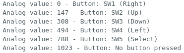 The actual numbers might vary slightly depending on your module.
Conclusion
The AD keyboard module is a solid choice for simple input control when working with Arduino. It's easy to set up, compact, and uses only one analog pin. You can use it to control menus on an LCD, play around with directional controls in basic games, move robots, or adjust values in your sketch. Once you test it and get a feel for how the analog values behave, you can start building more interactive and responsive projects without much hassle.
Credits
Official GitHub: https://github.com/hibit-dev/ad-keyboard


0 Comments