
Reading light levels with an LDR and Arduino

A light dependent resistor is a component that changes its electrical resistance according to how much light falls on it. Bright light makes it conduct easily, darkness makes it conduct poorly, and an Arduino can turn that difference into a number. It arrives in two forms. The raw component is a small disc with two legs, and it needs one extra resistor to work. The other form is a sensor module, a small board with the component already soldered on together with everything else the circuit needs, ready to connect to the Arduino with three or four jumper wires. Both versions do the same job and both show up in real projects. Automatic garden lights, night lights, display backlight dimming or simple daylight loggers all work on the same principle.
This article covers how the component behaves, how to wire either version to an Arduino, what the module adds on top of the raw part, and a set of sketches that go from printing readings in the Serial Monitor to switching a lamp on when the room gets dark.
Components
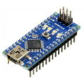
| 1x Arduino Nano (or another Arduino module)
|
| 1x Mini-breadboard
|
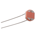
| 1x LDR Sensor
|
| Resistors kit
|
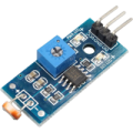
| 1x LDR Module
|
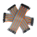
| Dupont wires
|
Resistance that follows the light
The light sensitive part is a zigzag track printed on the face of the disc. The spiral shape packs a long conductive path into a small area, and the material it is made from lets current through more easily as more light reaches it.
The resistance moves in the opposite direction to the light, so a high resistance means dark and a low resistance means bright. The swing between the two is large. A common hobby part sits somewhere around 1 MΩ in complete darkness, drops to roughly 10 kΩ under normal indoor lighting, and can fall below 1 kΩ with a phone torch pointed at it. That range of three orders of magnitude is what makes the part usable with a 10 bit converter without any amplification.
Photoresistors are sold in several diameters and sensitivity grades, and the numbers above shift with the model. A larger disc catches more light and reacts a bit faster, and different grades are tuned to sit in their useful range at different brightness levels. For most projects the exact model matters far less than measuring what a particular unit actually reads in the place it will be installed, since the thresholds in the code come from those measurements anyway.
Two more properties matter in practice. The component is not polarized, so the legs can be swapped without any consequence, and it works with alternating current as well as direct current. It is also a fairly slow device. Response times are measured in tens of milliseconds, and recovery from bright light back to a dark reading is slower than the other direction.
Wiring the sensor to Arduino
An Arduino analog pin measures voltage, not resistance. Connecting a bare LDR between 5 V and A0 does not give a usable reading, because with nothing else in the circuit there is no defined path to ground and the pin ends up floating. The resistance change has to become a voltage change first, and the standard way to do that is a voltage divider.
A voltage divider is two resistors in series across the supply, with the measurement taken from the point between them. The output voltage follows the ratio between the two:
Vout = Vin * R2 / (R1 + R2)
Putting the LDR as R1 and a fixed 10 kΩ resistor as R2 gives a node that rises toward 5 V as the LDR resistance falls. In darkness, with the LDR near 1 MΩ, the output is around 0.05 V and analogRead() returns something close to 10. Under room lighting, with both resistances near 10 kΩ, the output sits near 2.5 V and the reading lands around 512. Under a torch the reading climbs past 900.
On the breadboard that means three connections. One leg of the LDR goes to 5V. The other leg goes to a row that connects both to A0 and to one end of a 10 kΩ resistor. The free end of that resistor goes to GND.
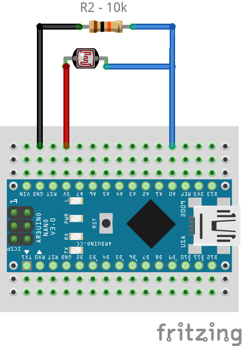 Swapping the LDR and the fixed resistor flips the behaviour, so the reading goes down as the light goes up. Neither arrangement is more correct than the other, it just changes which direction the numbers move, and the sketch has to match the wiring.
The value of the fixed resistor sets where the sensor is most sensitive. The divider gives its biggest voltage swing per unit of resistance change when the two resistances are similar, so a 10 kΩ resistor puts the useful range around typical indoor light. For a project that needs to distinguish shades of darkness, a larger fixed resistor of 47 kΩ or 100 kΩ pushes the sensitive region toward lower light levels. For a project working in bright sunlight, 1 kΩ makes more sense.
The module version of the same circuit
The modules skip all of the above. The divider is already built onto the board, so there is no breadboard, no loose resistor and no risk of swapping the two components around and reading the light the wrong way up. VCC goes to 5 V and GND goes to GND on every one of them, and the rest depends on the version.
Three versions are on sale:
The simplest one has three pins: VCC, GND and an analog output that goes to A0. It is the breadboard circuit already assembled and the readings behave exactly the same.
The second also has three pins: VCC, GND and a digital output. An LM393 comparator watches the divider and switches the digital pin between HIGH and LOW the moment the light passes a set point, so the board answers light or dark on its own. The reading itself never leaves the board, and
digitalRead()on any digital pin is enough to use it.The third has four pins and gives both outputs at once, AO going to A0 and DO going to a digital pin. It costs the same as the other two and keeps both options open, which makes it the safe choice while a project is still taking shape.
Both comparator boards carry a small blue potentiometer and a second LED that lights up when the digital output is active. The potentiometer is the sensitivity adjustment for that output. It sets the reference the comparator measures the light against, so turning the screw moves the brightness at which DO switches, and the LED changes state at the same moment, which makes the setting easy to dial in by hand. On the four pin board the analog output stays untouched, so AO keeps reporting the full range no matter where the screw sits.
The direction of the digital output varies between board revisions, and plenty of these modules go LOW when light is detected rather than HIGH, so the sensible approach is to print the value once and confirm how a particular board behaves.
Arduino code
The first sketch does nothing except print the converter output. It is worth running before anything else, because the numbers a specific sensor produces in a specific room are the basis for every threshold used later.
#define LDR_PIN A0

void setup()
{
  Serial.begin(9600);
}

void loop()
{
  int reading = analogRead(LDR_PIN);  // 0 to 1023 on a 10 bit board

  Serial.print("Light level: ");
  Serial.println(reading);

  delay(200);  // slow enough to read the output by eye
}
Open the Serial Monitor and set the baud rate to 9600 to match Serial.begin(). Cover the sensor with a hand and the number drops. Shine a phone torch on it and the number jumps close to the top of the scale. Write down the value in the darkest and brightest conditions the project will actually face, since those two numbers define the working range.
The printed value moves around by a few units even when the light looks perfectly steady. Some of that comes from the converter itself, and some from mains powered lamps, which flicker 50 or 60 times a second faster than any eye can follow. Taking several readings in a row and using their average smooths the output and costs almost nothing:
int readAverage(int pin, int samples) {
  long total = 0;

  for (int i = 0; i < samples; i++) {
    total += analogRead(pin);
    delay(2);
  }

  return total / samples;
}
Calling readAverage(ldrPin, 10) instead of analogRead(ldrPin) gives a much steadier number, at the cost of about 20 ms per reading. The Serial Plotter, in the same Tools menu as the Serial Monitor, draws the values as a graph and makes the difference easy to see.
Getting analog and digital at once
With a four pin module connected, the sketch below prints both outputs side by side. That makes it easy to turn the potentiometer and watch exactly where the digital pin changes state relative to the analog value.
#define ANALOG_PIN A0
#define DIGITAL_PIN 2

void setup()
{
  Serial.begin(9600);

  pinMode(DIGITAL_PIN, INPUT);
}

void loop()
{
  int level = analogRead(ANALOG_PIN);   // continuous light level
  int state = digitalRead(DIGITAL_PIN); // comparator output

  Serial.print("AO: ");
  Serial.print(level);
  Serial.print("  DO: ");
  Serial.println(state);

  delay(200);
}
Turning the potentiometer clockwise or counterclockwise moves the switching point up or down the analog scale. Noting the AO value at the exact moment DO changes gives a calibrated threshold that can be reused in code, which is handy for a project that needs to work in a specific location.
Practical limitations
The reading follows the light closely, but it is not a measurement. A value of 400 cannot be turned into lux, and it will not match what another sensor reports under the same lamp. It only makes sense next to other readings from the same sensor in the same spot, which is why thresholds always come from testing.
Three things are worth keeping in mind:
The first is unit to unit variation. Two parts from the same bag can read noticeably differently under identical light, and the tolerances quoted for these cells are wide. Code calibrated against one sensor may need new thresholds after a replacement, which is a real annoyance in anything built in quantity.
The second is drift over time and temperature. The resistance moves with ambient temperature, which goes unnoticed indoors and shows up in an outdoor installation across a year. There is also a slow settling after a big change in brightness, so the reading takes a moment to arrive at its final value.
The third is colour. The material reacts most strongly to green light, close to the middle of human vision, and hardly at all to infrared, which rules it out for anything involving an infrared remote or an infrared beam.
For anything that reacts to light getting brighter or darker, none of this matters, since the code works from the reading going up or down. Real lux values are a different story, and they need a digital light sensor built for that purpose, which reports calibrated numbers straight away.
Conclusion
An LDR is a simple way to bring light into an Arduino project with one extra resistor, or with none at all when the sensor comes on a module. It marks the point where a board stops reacting only to buttons and starts reacting to the room around it. That shift is what turns a circuit into something that runs on its own, without anyone having to intervene.
Credits
Official GitHub: https://github.com/hibit-dev/light-sensor




0 Comments