Pull-up and Pull-down resistors
A resistor is a passive two-terminal electrical component that implements electrical resistance as a circuit element. In electronic circuits, resistors are used to reduce current flow and adjust signal levels among other uses. Resistance is measured in Ohm with a sign of Ω.
A microcontroller (e.g. Arduino) utilizes I/O signals for communication with external hardware devices, where the most commonly known being GPIO. As a reminder, digital logic circuits have three logic states: high, low and floating (or high impedance). When there’s nothing connected to your GPIO pins, your program will read a floating impedance state, which we do not want. To achieve either high or low states, we’ll have to implement pull-up or pull-down resistors in our digital circuit.
What are Pull-up resistors?
Pull-up resistors are fixed value resistors used between the connection of a voltage supply and a particular pin in a digital logic circuit. More commonly paired with switches, its purpose is to ensure the voltage between GND and VCC is actively controlled when the switch is open.
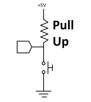
If you require a low default impedance state and wish to pull the signal to high, pull up resistors are the ones to use.
What are Pull-down resistors?
Similarly to pull-up resistors, pull-down resistors ensure the voltage between VCC and a microcontroller pin is actively controlled when the switch is open. However, instead of pulling a pin to a high value, such resistors pull the pin to a low valued instead. Though being less commonly used, a pull-down resistor is still a valid option.
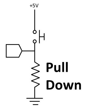
If you require a high default impedance state and wish to pull the signal to low, pull up resistors are the ones to use.
Pull-up and Pull-down resistor values
In bipolar logic families which operate at operating at 5V, the typical pull-up resistor value is 1-5 kΩ. Similarly to how we calculate resistance for a normal resistor, we’ll use the formula in Ohms law to know the actual value:
Resistance = Voltage/Current
For pull up resistors, the formula for calculating actual value is: Rpull-up = (Vsupply – Vmin) / Isink
Vsupply is the supply voltage
Vmin is minimum accepted voltage as high
Isink is the maximum current sinked by the digital pin
Formula for calculating actual value for pull-down resistors: Rpull-down = (Vmax – 0) / Isource
Vmax is the maximum voltage is accepted as logic low
Isource is the maximum current sourced by the digital pin.
Arduino internal Pull-up resistor
On each board there are Arduino internal pull-up resistors built-in, they just need to be turned on in the sketch, usually in setup() using:
pinMode(PIN_NUMBER, INPUT_PULLUP);
When using any kind of open inputs with an Arduino such as switches and push buttons a pull-up resistor is needed for reliable operation. These resistors hold the I/O pin at a known value until the switch forces the I/O pin to a different known value.


0 Comments