Getting real-time position using MPU9250
MPU-9250 is one of the most advanced combined accelerometer, gyroscope and compass small size sensors currently available. It replaces the popular MPU-9150 lowering the power consumption, improving gyro noise and compass full scale range performance. It has many advanced features, including low pass filtering, motion detection and even a programmable specialized processor.
MPU9250 sensors
Internally it includes the MPU-6500, which contains a 3-axis gyroscope plus a 3-axis accelerometer, and the AK8963, the market leading 3-axis digital compass. The MPU-9250 uses 16-bit analog-to-digital converters (ADCs) for digitizing all 9 axes.
The MPU-9250 is a high performance accelerometer, gyroscope and magnetometer option for use in applications such as gesture recognition, self-balancing robots, cell phones, fitness monitoring and similar applications where detection of movement direction and magnitude along with rotation is desired. In reading MPU9250 sensors with Arduino article we've introduced the module and how to interact with it. As well as, the use of complementary filter to get the relative position. Let's now see the full power of MPU9250 module: the mixed use of gyroscope, accelerometer and magnetometer to get real-time accurate position.
Gyroscope
A gyroscope is a device used for measuring or maintaining orientation and angular velocity. Measured in degrees (or radian) per second, angular velocity is the change in the rotational angle of the object per unit of time.
Acceletometer
Accelerometer sensors are integrated circuits (ICs) that measure acceleration, which is the change in speed per unit time. Measuring acceleration makes it possible to obtain information such as object inclination and vibration.
Commonly, g is used as a unit for acceleration, relative to standard gravity (1g = 9.80665m/s2).
Magnetometer
Magnetometer provides information about the magnetic field detected by the device sensor, and in theory, can expose location of a user. The magnetometer sensor measures the magnetic field for all three physical axes (x, y, z) in μT (micro Tesla).
Components
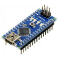
| 1x Arduino Nano (or another Arduino module) $3.39 |
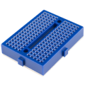
| 1x Mini Breadboard
|
| 1x MPU9250 $7.22 |
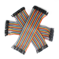
| Dupont wires
|
| I2C library |


Wiring schema
Connect the power supply pins and SDA, SCL pins according to the connection diagram shown below.
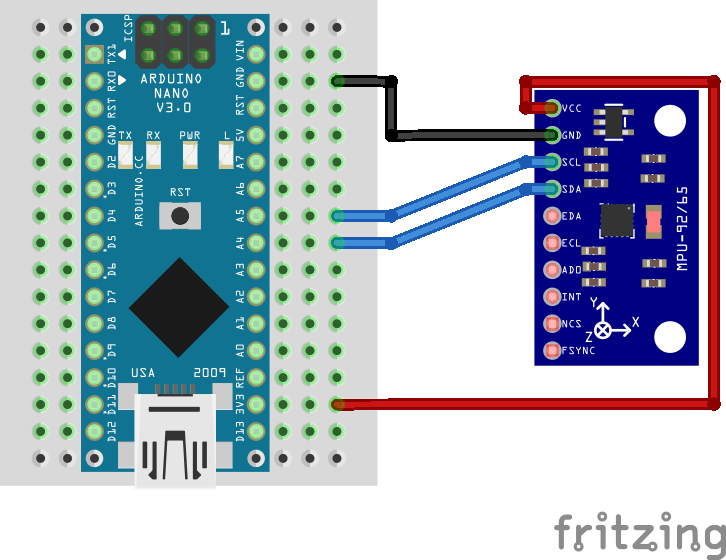
Note: the module operates with 3.3 volts, although some versions have a regulator that allows to connect it to 5V. Make sure to check your module specification before using it.
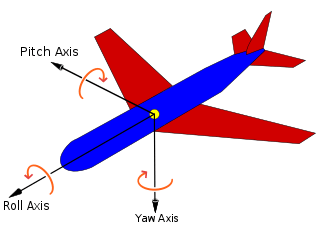
Relative and absolute orientation
Relative orientation is the recovery of the position and orientation of one object relative to another. Depending on the direction there are three types of angular rate measurements:
Yaw: the horizontal rotation on a flat surface when seen the object from above.
Pitch: vertical rotation as seen the object from front.
Roll: horizontal rotation when seen the object from front.
A graphical representation for each axis using a plane:
The absolute orientation is one of the common use-cases of a magnetometer and represents an orientation stationary (fixed to the magnetic field vector and gravity vector) to the Earth plane.
Noise and errors
In the ideal word, sensors data with applied formulas would provide us precise and exact angles. The reality is different as some factors affect the sensors output.
Typically, when you move around with an accelerometer it experiences movement accelerations. Additional acceleration values may affect the orientation accuracy. Another accelerometer related problem is the noise: unwanted disturbance in an electrical signal. The accelerometer is able to measure any angle, however its readings are noisy and have a certain margin of error even with a low pass filter.
On the other hand, gyroscopes are subject to bias instabilities, in which the initial zero reading of the gyroscope will cause drift over time due to integration of inherent imperfections and noise within the device.
Magnetometers are absolutely essential for correcting gyro drift in applications that require absolute orientation through sensor fusion. Magnetometer problem is their non-ideal response surfaces and location dependency.
Getting real time position
There are different algorithms to solve errors and noise problem. We are going to make use of quaternions. Quaternions are used in pure mathematics but also have practical uses in applied mathematics, particularly for calculations involving three-dimensional rotations. They can be used alongside other methods of rotation, such as Euler angles and rotation matrices, or as an alternative to them, depending on the application. The use of MPU9250 library rid us of understanding all the complexity of quaternions and the implementation is already done.
Magnetic declination
Magnetic declination should be set depending on where you are to get accurate data. You can find magnetic declination in your city here.
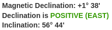
Note that the declination here is currently 1˚ 38'. The provided format needs to be converted to decimal degrees for the code. There are 60 minutes per degree, 38 of them is 38/60 of a degree, i.e., 0.63. The declination in decimal format for 1˚ 38' is 1.63. Update the code MAGNETIC_DECLINATION constant with the declination for your location.
Magnetic calibration
There is simple way to calibrate automatically and correct some of the errors of magnetometer data. Move slowly the sensor in a figure eight pattern and keep track of the minimum and maximum field measured in each of the six principal directions. The average can be subtracted from the subsequent data which amounts to re-centering the response surface on the origin. The library has calibration function that will automatically do it for us, we just need to move the sensor in a figure eight when calibration starts.
Install Arduino library for MPU9250
To interact with MPU9250 module we can use raw implementation or make use of existing libraries. The library provides an interface to communicate with the module saving us a lot of time. Another advantage is robust code base tested and improved by the community during years. We recommend to make use of the library and avoid implementing everything from scratch. It can be downloaded from our official repository.
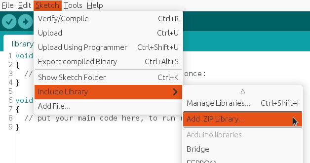
To import a library, open the Arduino IDE, go to Sketch > Include Library > Add .ZIP Library and select the library file downloaded from our GitHub repository.
Then you can simply use include statement:
#include "MPU9250.h"
It will include the library with predefined functions to interact with MPU9250.
Arduino code
The code below is straightforward as we used a library that provides clear interface to interact with MPU9250 module. In setup function we configure and calibrate the module and print output every INTERVAL_MS_PRINT milliseconds in the loop.
#include "MPU9250.h"

#define MPU9250_IMU_ADDRESS 0x68

#define MAGNETIC_DECLINATION 1.63 // To be defined by user
#define INTERVAL_MS_PRINT 1000

MPU9250 mpu;

unsigned long lastPrintMillis = 0;

void setup()
{
  Serial.begin(115200);
  Wire.begin();

  Serial.println("Starting...");

  MPU9250Setting setting;

  // Sample rate must be at least 2x DLPF rate
  setting.accel_fs_sel = ACCEL_FS_SEL::A16G;
  setting.gyro_fs_sel = GYRO_FS_SEL::G1000DPS;
  setting.mag_output_bits = MAG_OUTPUT_BITS::M16BITS;
  setting.fifo_sample_rate = FIFO_SAMPLE_RATE::SMPL_250HZ;
  setting.gyro_fchoice = 0x03;
  setting.gyro_dlpf_cfg = GYRO_DLPF_CFG::DLPF_20HZ;
  setting.accel_fchoice = 0x01;
  setting.accel_dlpf_cfg = ACCEL_DLPF_CFG::DLPF_45HZ;

  mpu.setup(MPU9250_IMU_ADDRESS, setting);

  mpu.setMagneticDeclination(MAGNETIC_DECLINATION);
  mpu.selectFilter(QuatFilterSel::MADGWICK);
  mpu.setFilterIterations(15);

  Serial.println("Calibration will start in 5sec.");
  Serial.println("Please leave the device still on the flat plane.");
  delay(5000);

  Serial.println("Calibrating...");
  mpu.calibrateAccelGyro();

  Serial.println("Magnetometer calibration will start in 5sec.");
  Serial.println("Please Wave device in a figure eight until done.");
  delay(5000);

  Serial.println("Calibrating...");
  mpu.calibrateMag();

  Serial.println("Ready!");
}

void loop()
{
  unsigned long currentMillis = millis();

  if (mpu.update() && currentMillis - lastPrintMillis > INTERVAL_MS_PRINT) {
    Serial.print("TEMP:\\t");
    Serial.print(mpu.getTemperature(), 2);
    Serial.print("\\xC2\\xB0"); //Print degree symbol
    Serial.print("C");
    Serial.println();

    Serial.print("Pitch:\\t");
    Serial.print(mpu.getPitch());
    Serial.print("\\xC2\\xB0"); //Print degree symbol
    Serial.println();

    Serial.print("Roll:\\t");
    Serial.print(mpu.getRoll());
    Serial.print("\\xC2\\xB0"); //Print degree symbol
    Serial.println();

    Serial.print("Yaw:\\t");
    Serial.print(mpu.getYaw());
    Serial.print("\\xC2\\xB0"); //Print degree symbol
    Serial.println();

    Serial.println();

    lastPrintMillis = currentMillis;
  }
}
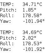
Testing
The serial monitor will print last available sensors data every INTERVAL_MS_PRINT milliseconds (in the example above, once per second) and it should be similar to:
Usually the orientation is drawn on the physical module so you can easily detect pitch and roll.
Credits
Official GitHub: https://github.com/hibit-dev/mpu9250
Official MPU9250 library GitHub: https://github.com/hideakitai/MPU9250


4 Comments
PrithivRaj Reply
i'm trying to calculate Orientation parameter terminals like Orientation roll, pitch, yaw, qw, qx, qy, qz by using of MPU 9250 sensor outputs. if any body knows how to do that please let me know. Thankyou.
HiBit Reply
We used an existing library for this. You can see how it was implemented in the code snippet above.
It is also accessible in our GitHub repository.
S I Reply
Came from more simple example of your code: used your i2c library. Quite good, but it took some time to understand What's wrong with yaw position. Okay. Tried to dig further. Came here. Surprise-surprise! My MPU Mag has default address: 0x0C but system not working with MPU9250. While trying to connect to MAG: it gives i2c error 2. Connection to MPU itself - returns false. Can't understand what could go wrong? The same adress for two chips...
HiBit Reply
It's quite possible that there's something wrong with the module. We've seen other people run into the same problem before, and it turned out that there was a problem with one of the chips inside. You might want to try using a different module to see if that resolves the issue for you.