Complementary filter and relative orientation with MPU6050
The MPU-60X0 is the world's first integrated 6-axis MotionTracking device that combines a 3-axis gyroscope, 3-axis accelerometer and a Digital Motion Processor (DMP) all in a small package. It helps to measure velocity, orientation, acceleration, displacement and other motion like features
The MPU-6050 features three 16-bit analog-to-digital converters (ADCs) for digitizing the gyroscope outputs and three 16-bit ADCs for digitizing the accelerometer outputs. For precision tracking of both fast and slow motions, the parts feature a user-programmable gyroscope full-scale range and a user-programmable accelerometer full-scale range.
The MPU-6050 is a high performance accelerometer, gyroscope and magnetometer option for use in applications such as gesture recognition, self-balancing robots, cell phones, fitness monitoring and similar applications where detection of movement direction and magnitude along with rotation is desired. In reading MPU6050 sensors with Arduino article we've introduced the module and how to interact with it, now we will see how to use extracted data and get relative orientation.
Components
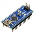
| 1x Arduino Nano (or another Arduino module)
|
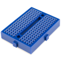
| 1x Mini Breadboard
|
| 1x MPU6050 $2.00 |
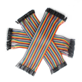
| Dupont wires
|
| I2C library |


Wiring schema
Connect the power supply pins and SDA, SCL pins according to the connection diagram shown below.
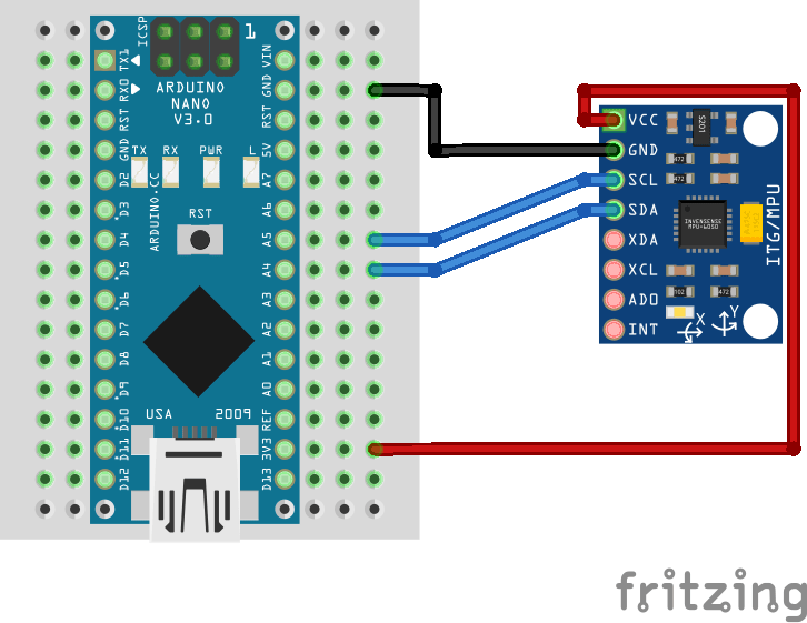
Note: the module operates with 3.3 volts, although some versions have a regulator that allows to connect it to 5V. Make sure to check your module specification before using it.
Relative orientation
Relative orientation is the recovery of the position and orientation of one object relative to another. Depending on the direction there are three types of angular rate measurements:
Yaw: the horizontal rotation on a flat surface when seen the object from above.
Pitch: vertical rotation as seen the object from front.
Roll: horizontal rotation when seen the object from front.
A graphical representation for each axis using a plane:

Angles can not be directly extracted from MPU-9250 module but with correct formulas we can obtain them.
Accelerometer angles
Commonly, g is used as a unit for acceleration, relative to standard gravity (1g = 9.80665m/s2). Acceleration for perfectly aligned IMU will be 1g for Z axis. Terrestrial gravity and trigonometry allow to use the accelerometer readings and know the angle of inclination. The formulas to calculate the angles are:
pitch = atan2(accelerometer_x, sqrt(accelerometer_y^2 + accelerometer_z^2))
roll = atan2(accelerometer_y, sqrt(accelerometer_x^2 + accelerometer_z^2))
You can not obtain yaw angles from accelerometer because yaw motions occur in a plane and so no matter what X and Y readings you have.
Gyroscope angles
The gyroscope measures the angular velocity, i.e., the number of degrees rotated in a unit of time. Having initial angle of the IMU, angular velocity and the time passed between samples, we can know the angle change. It's very similar to linear speed, that multiplied by time give us the total distance passed. The formulas to calculate the angles are:
pitch = pitch + gyroscope_x * elapsed_time
roll = roll + gyroscope_y * elapsed_time
yaw = yaw + gyroscope_z * elapsed_time
Where elapsed time is the time interval between samples. The Z axis is usually ignored, since we don't have yaw angle from accelerometer and we can not rely only on gyroscope sensor.
Noise and errors
In the ideal word, sensors data with applied formulas would provide us precise and exact angles. The reality is different as some factors affect the sensors output.
Typically, when you move around with an accelerometer it experiences movement accelerations. Additional acceleration values may affect the orientation accuracy. Another accelerometer related problem is the noise: unwanted disturbance in an electrical signal. The accelerometer is able to measure any angle, however its readings are noisy and have a certain margin of error even with a low pass filter.
On the other hand, gyroscopes are subject to bias instabilities, in which the initial zero reading of the gyroscope will cause drift over time due to integration of inherent imperfections and noise within the device.
So, what can we do? There are different algorithms to solve this problems. The one we are going to use is known as complementary filter. Idea behind complementary filter is to take slow moving signals from accelerometer and fast moving signals from a gyroscope and combine them. It is ideal to implement with Arduino: easy to use, low cost of processing and good precision.
Complementary filters
The complementary filter can be thought of as a union of two different filters: a high-pass filter for the gyroscope and a low-pass filter for the accelerometer. The first lets only pass the values above a certain limit, unlike the low-pass filter, which only allows those below.
Accelerometer gives a good indicator of orientation in static conditions and gyroscope gives a good indicator of tilt in dynamic conditions. The formula resulting from combining the two filters is:
angle = (1 - α) * (angle + gyroscope * dt) + α * accelerometer
A common value for α is 0.98, which means that 98% of the weight lays on the gyroscope measurements.
pitch = 0.98 * (pitch + gyroscope_x * dt) + 0.02* accelerometer_x
roll = 0.98 * (roll + gyroscope_y * dt) + 0.02* accelerometer_y
As the data changes very rapidly we can sample for some amount of time and take the average for more precise results.
Install Arduino library for I2C
We will use I2C protocol to interact with registers and read/write data. The I2C library provides a very simple interface for that purpose and can be reused in other projects that use I2C protocol. It can be downloaded from our official repository.
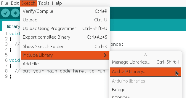
To import a library, open the Arduino IDE, go to Sketch > Include Library > Add .ZIP Library and select the library file downloaded from our GitHub repository.
Then you can simply use include statement:
#include "I2C.h"
It will include the library with predefined functions to interact with registers.
Arduino code
We are going to reuse most of the code generated from the raw sensors reading. To be more specific, everything related with data reading and normalization, together with defined structs.
The sampling theorem states that a real signal which is band-limited to f HZ can be reconstructed without error from samples taken uniformly at a rate R > 2f. So, it's important to choose an output rate that will be at least two times the DLPF, otherwise the data will be corrupted (aliased).
A new structure has been defined, called angle, to represent object position. Make sure to follow the previous step and import I2C library in order to use it with the include statement:
#include "Wire.h"
#include "I2C.h"

#define MPU6050_IMU_ADDRESS 0x68

#define GYRO_FULL_SCALE_250_DPS  0x00
#define GYRO_FULL_SCALE_500_DPS  0x08
#define GYRO_FULL_SCALE_1000_DPS 0x10
#define GYRO_FULL_SCALE_2000_DPS 0x18

#define ACC_FULL_SCALE_2G  0x00
#define ACC_FULL_SCALE_4G  0x08
#define ACC_FULL_SCALE_8G  0x10
#define ACC_FULL_SCALE_16G 0x18

#define TEMPERATURE_OFFSET 21 // As defined in documentation

#define INTERVAL_MS_PRINT 1000

#define G 9.80665

struct gyroscope_raw {
  int16_t x, y, z;
} gyroscope;

struct accelerometer_raw {
  int16_t x, y, z;
} accelerometer;

struct temperature_raw {
  int16_t value;
} temperature;

struct {
  struct {
    float x, y, z;
  } accelerometer, gyroscope;

  float temperature;
} normalized;

struct angle {
  float x, y, z = 0;
};

angle position;

unsigned long lastPrintMillis = 0;
unsigned long lastSampleMicros = 0;

void setup()
{
  Wire.begin();
  Serial.begin(115200);

  // Data Output Rate = 1000 / (1 + SRD)
  // Output rate must be at least 2x DLPF rate
  I2CwriteByte(MPU6050_IMU_ADDRESS, 25, 0x01); // Set the SRD to 1
  I2CwriteByte(MPU6050_IMU_ADDRESS, 26, 0x01); // Set the DLPF to 184HZ by default
  I2CwriteByte(MPU6050_IMU_ADDRESS, 27, GYRO_FULL_SCALE_1000_DPS); // Configure gyroscope range
  I2CwriteByte(MPU6050_IMU_ADDRESS, 28, ACC_FULL_SCALE_2G); // Configure accelerometer range
  I2CwriteByte(MPU6050_IMU_ADDRESS, 56, 0x01); // Enable interrupt pin for raw data
}

void loop()
{
  unsigned long currentMillis = millis();

  readSample();

  if (currentMillis - lastPrintMillis > INTERVAL_MS_PRINT) {
    Serial.print("TEMP:\\t");
    Serial.print(normalized.temperature, 2);
    Serial.print("\\xC2\\xB0"); //Print degree symbol
    Serial.print("C");
    Serial.println();

    Serial.print("Pitch:\\t");
    Serial.print(getPitch());
    Serial.print("\\xC2\\xB0"); //Print degree symbol
    Serial.println();

    Serial.print("Roll:\\t");
    Serial.print(getRoll());
    Serial.print("\\xC2\\xB0"); //Print degree symbol
    Serial.println();

    Serial.println();

    lastPrintMillis = currentMillis;
  }
}

bool readSample()
{
  if (isImuReady() == false) {
    return false;
  }

  unsigned long sampleMicros = (lastSampleMicros > 0) ? micros() - lastSampleMicros : 0;

  lastSampleMicros = micros();

  readRawImu();

  normalize(gyroscope);
  normalize(accelerometer);
  normalize(temperature);

  angle accelerometer = calculateAccelerometerAngles();
  angle gyroscope = calculateGyroscopeAngles(sampleMicros);

  detectPitch(gyroscope, accelerometer);
  detectRoll(gyroscope, accelerometer);

  return true;
}
Note: the snippet is part of Arduino project located in our GitHub repository with the code separated in different logical files.
Testing
The serial monitor will print latest available sensors data every INTERVAL_MS_PRINT milliseconds (in the example above, once per second) and it should be similar to:
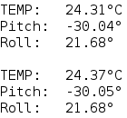
Usually the orientation is drawn on the physical module so you can easily detect pitch and roll.
Credits
Official GitHub: https://github.com/hibit-dev/mpu6050


2 Comments
tarek shawki Reply
hello sir i am so great full for this kind of work , i'm trying to make tilt level indicator which will be placed on top of corn tank , i tested this code and it works perfect but i am facing a problem with readings when i cut the power off then turn it on all the readings are zeroes and it does not matter if i upload the code again it turns zeroes, i must then upload the mpu6050 code in the examples then upload your code to get it to work again.... i am trying to figure out the problem but i cant, can you suggest me what to do
HiBit Reply
Thank you, very appreciated!
The issue is likely that the MPU6050 isn't properly initialized after power-up. Make sure the
setup()function runs completely each time the device is powered on, and consider adding a small delay before using the sensor.