How to use the NRF24L01 module with Arduino
Having two or more Arduino boards be able to communicate with each other wirelessly over a distance opens lots of possibilities like remotely monitoring sensor data, controlling robots, home automation and the list goes on. A good, reliable and inexpensive solution is NRF24L01.
The NRF24L01+ is a newer version of the NRF24L01, capable of doing an extra 250kbps of on-air data rate while the one without “+” has only 1Mbps and 2Mbps. Both versions can be mixed together as long as 1 or 2 MBps is being used as the data rate.
Components
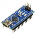
| 2x Arduino Nano (or another Arduino module)
|
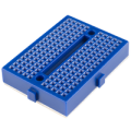
| 2x Mini-breadboard
|
| 2x NRF24L01 (or NRF24L01+ or NRF24L01+PA+LNA)
|
| 2x NRF24L01 adapter (recommended) $1.22 |
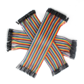
| Dupont wires
|
| RF24 official library |


NRF24L01 vs NRF24L01+PA+LNA
The NRF24L01 module strictly needs 3.3V but the logic pins are 5V tolerant. That why we recommend to use the NRF24L01 adapter which acts as regulator, keep the voltage stable, apply filtering and reduce noises.
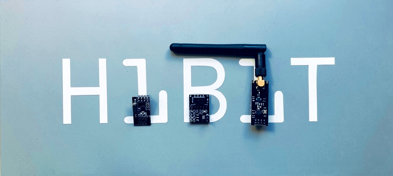
The first version (on the left) uses on-board antenna. This allows for a more compact version of the breakout. With this version, you’ll be able to communicate over a distance of 100 meters (range indoors, especially through walls, will be slightly weakened). We will use it for the receiver.
The second version (on the right) integrates the PA, LNA, and transmit-receive switching circuitry. This range extender chip along with external antenna helps the module achieve about 1000m. We will use it for the transmitter.
The adapter works identically for both versions and has the same pinout as original boards.
Wiring schema
The NRF24L01 module communicates with the Arduino using SPI protocol. The module acts as an SPI slave, which means that it can only be used with devices that have dedicated SPI communication lines. This means that the MOSI, MISO, and SCK pins must be connected to their corresponding pins on the microcontroller. We've used Arduino Nano and these pins are as follows:
MOSI: Arduino Nano D11
MISO: Arduino Nano D12
SCK: Arduino Nano D13
The CE and the CSN pins can be connected to Arduino Nano D9 and D10 respectively (you can use any pins). However, pin D10 is a special pin, it must be set as OUTPUT for the Arduino Nano to operate as an SPI master. In case you are using different Arduino board, it is advisable to check the Arduino official documentation before proceeding.
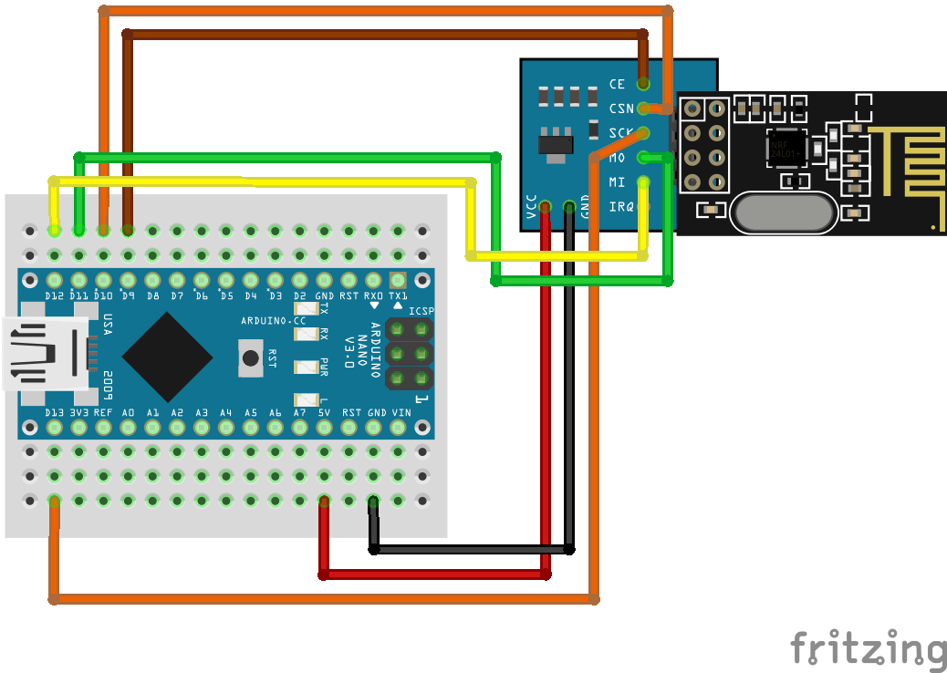
Note: you need to make two of these circuits. One acts as a transmitter and the other as a receiver. The wiring for both is identical.
Install Arduino library for nRF24L01
The library will provide you an interface to communicate with the module saving you a lot of time and providing a robust code base tested and improved by the community during years. You can download the library from our official repository.
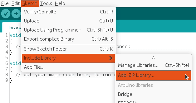
To import it, open the Arduino IDE, go to Sketch > Include Library > Add .ZIP Library and then select the file that you just downloaded.
Then you can simply use include statement:
#include "RF24.h"
#include "nRF24L01.h"
It will include the library with predefined functions to interact with module.
Transmitter Arduino code
We've defined a struct (called payload) which will be sent every INTERVAL_MS_TRANSMISSION milliseconds.
setup() function initiate the module as transmitter with the provided configuration.
loop() function will take care of updating the payload values and sending them.
#include "SPI.h"
#include "RF24.h"
#include "nRF24L01.h"

#define CE_PIN 9
#define CSN_PIN 10

#define INTERVAL_MS_TRANSMISSION 250

RF24 radio(CE_PIN, CSN_PIN);

const byte address[6] = "00001";

//NRF24L01 buffer limit is 32 bytes (max struct size)
struct payload {
  byte data1;
  char data2;
};

payload payload;

void setup()
{
  Serial.begin(115200);

  radio.begin();

  //Append ACK packet from the receiving radio back to the transmitting radio
  radio.setAutoAck(false); //(true|false)
  //Set the transmission datarate
  radio.setDataRate(RF24_250KBPS); //(RF24_250KBPS|RF24_1MBPS|RF24_2MBPS)
  //Greater level = more consumption = longer distance
  radio.setPALevel(RF24_PA_MAX); //(RF24_PA_MIN|RF24_PA_LOW|RF24_PA_HIGH|RF24_PA_MAX)
  //Default value is the maximum 32 bytes
  radio.setPayloadSize(sizeof(payload));
  //Act as transmitter
  radio.openWritingPipe(address);
  radio.stopListening();
}

void loop()
{
  payload.data1 = 123;
  payload.data2 = 'x';

  radio.write(&payload, sizeof(payload));

  Serial.print("Data1:");
  Serial.println(payload.data1);

  Serial.print("Data2:");
  Serial.println(payload.data2);

  Serial.println("Sent");

  delay(INTERVAL_MS_TRANSMISSION);
}
Receiver Arduino code
We will be listening for the struct defined in the transmitter (called payload). The connection will be considered as lost after INTERVAL_MS_SIGNAL_LOST milliseconds.
setup() function initiate the module as receiver with the provided configuration.
loop() function will take care of listening for the payload and handling it.
lostConnection() function will handle the lost connection to prevent unwanted behavior.
#include "SPI.h"
#include "RF24.h"
#include "nRF24L01.h"

#define CE_PIN 9
#define CSN_PIN 10

#define INTERVAL_MS_SIGNAL_LOST 1000
#define INTERVAL_MS_SIGNAL_RETRY 250

RF24 radio(CE_PIN, CSN_PIN);

const byte address[6] = "00001";

//NRF24L01 buffer limit is 32 bytes (max struct size)
struct payload {
  byte data1;
  char data2;
};

payload payload;

unsigned long lastSignalMillis = 0;

void setup()
{
  Serial.begin(115200);

  radio.begin();

  //Append ACK packet from the receiving radio back to the transmitting radio
  radio.setAutoAck(false); //(true|false)
  //Set the transmission datarate
  radio.setDataRate(RF24_250KBPS); //(RF24_250KBPS|RF24_1MBPS|RF24_2MBPS)
  //Greater level = more consumption = longer distance
  radio.setPALevel(RF24_PA_MIN); //(RF24_PA_MIN|RF24_PA_LOW|RF24_PA_HIGH|RF24_PA_MAX)
  //Default value is the maximum 32 bytes1
  radio.setPayloadSize(sizeof(payload));
  //Act as receiver
  radio.openReadingPipe(0, address);
  radio.startListening();
}

void loop()
{
  unsigned long currentMillis = millis();

  if (radio.available() > 0) {
    radio.read(&payload, sizeof(payload));

    Serial.println("Received");

    Serial.print("Data1:");
    Serial.println(payload.data1);

    Serial.print("Data2:");
    Serial.println(payload.data2);

    lastSignalMillis = currentMillis;
  }

  if (currentMillis != 0 && currentMillis - lastSignalMillis > INTERVAL_MS_SIGNAL_LOST) {
    lostConnection();
  }
}

void lostConnection()
{
  Serial.println("We have lost connection, preventing unwanted behavior");

  delay(INTERVAL_MS_SIGNAL_RETRY);
}
Testing
Remember that we must build two circuits with identical wiring.
On the one hand, we will upload the transmitter code. It will generate the message payload and send it every INTERVAL_MS_TRANSMISSION.
On the other hand, we will upload the receiver code. It will listen for the message payload and process it. The serial monitor will output something similar to:
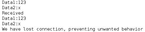
The last line indicates lost connection (after INTERVAL_MS_SIGNAL_LOST milliseconds with no signal). In our case, it was an expected behavior. In real life the signal can be lost due to many known and unknown reasons, we should be able to control that and act with corrections (in lostConnection() function).
Credits
Official GitHub: https://github.com/hibit-dev/nrf24l01
Official nRF24 GitHub: https://github.com/nRF24


6 Comments
Lobie Reply
When you write
"However, pin D10 is a special pin, it must be set as OUTPUT for the Arduino Nano to operate as an SPI master."
what do you mean ?
I went through the code expecting to find a pinMode(10, OUTPUT) ... but I don't find my understanding implemented.
Furthermore, if that is CSN that requires it, why does CE not require it ?
incidentally, before I found this post I had tried adding such a line in my code, and it did not help.
HiBit Reply
The D10 pin has a specific function; it must be set as an output for the Arduino to operate as the master in an SPI communication protocol. In the provided wiring and code, the pin is already functioning as an output.
Lobie Reply
Thank you. I have been searching everywhere for the usage to reduce data speed and turn ack off. Yes we need a simple get started code example, but we also need an example that shows all the variables. I am stuck with a setup, seems to be ok, I have done everything suggested that I can find, and yet I still have 2 modules that are transfering no data? From all that I have read so far, the implementation of "lost signal" is brilliant.
HiBit Reply
I suggest verifying the wiring to confirm that all components are correctly connected, followed by re-uploading the code. The examples provided in the post have been tested and are operational. Please consider that there might be a physical problem, such as a damaged or defective module.
JimS Reply
It's frustrating when people post code in tutorials to help others then their code has no comments and extra code rather than the bare minimum needed to explain what they are trying to illustrate. It may make perfect sense to you (because you wrote it) but it is a burden trying to weed through all the unnecessary code and understand your code
HiBit Reply
Hi JimS and thanks for your feedback.
We always try to use ubiquitous language so the code is self-explanatory. In this concrete case we also have comments to show available setup options and some of the limitations. Besides, output printing can be useful to better understand what each variable contains.
Whatever the case may be, any specific doubt can be asked and answered here in the comments.