Reading MPU6050 sensors with Arduino
The MPU-60X0 is the world's first integrated 6-axis MotionTracking device that combines a 3-axis gyroscope, 3-axis accelerometer and a Digital Motion Processor (DMP) all in a small package. It helps to measure velocity, orientation, acceleration, displacement and other motion like features
MPU6050 sensors
The MPU-6050 features three 16-bit analog-to-digital converters (ADCs) for digitizing the gyroscope outputs and three 16-bit ADCs for digitizing the accelerometer outputs. For precision tracking of both fast and slow motions, the parts feature a user-programmable gyroscope full-scale range and a user-programmable accelerometer full-scale range.
Gyroscope
A gyroscope is a device used for measuring or maintaining orientation and angular velocity. Measured in degrees (or radian) per second, angular velocity is the change in the rotational angle of the object per unit of time.
Depending on the direction there are three types of angular rate measurements:
Yaw: the horizontal rotation on a flat surface when seen the object from above.
Pitch: vertical rotation as seen the object from front.
Roll: horizontal rotation when seen the object from front.
Acceletometer
Accelerometer sensors are integrated circuits (ICs) that measure acceleration, which is the change in speed per unit time. Measuring acceleration makes it possible to obtain information such as object inclination and vibration.
Commonly, g is used as a unit for acceleration, relative to standard gravity (1g = 9.80665m/s2).
Components
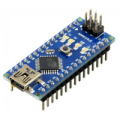
| 1x Arduino Nano (or another Arduino module) $3.41 |
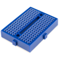
| 1x Mini Breadboard
|
| 1x MPU6050 $2.00 |
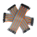
| Dupont wires
|
| I2C library |


Wiring schema
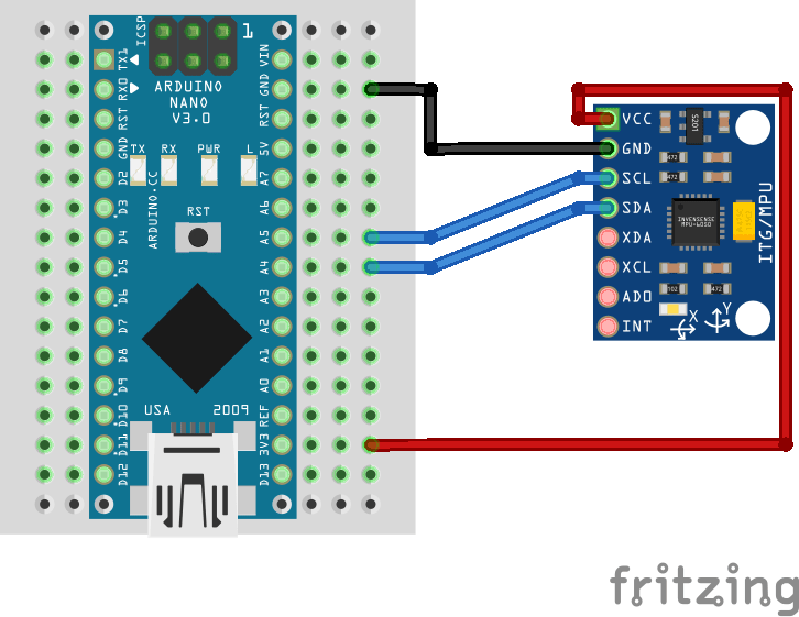
MPU6050 module has 10 pins but for basic usage we will only need 4.
PIN | Description |
|---|---|
VCC | Power supply pin |
GND | Ground pin |
SCL | I2C Serial Clock/SPI Serial Clock pin |
SDA | I2C Serial Data/SPI Serial Data pin |
XDA | I2C Serial Data input for external sensors connection pin |
XCL | I2C Master Serial Clock for external sensors connection pin |
AD0 | I2C Address/Serial data out pin |
INT | Interrupt pin |
As mentioned, for basic usage connect the power supply pins and SDA, SCL pins according to the connection diagram shown below:
Interpreting data
We have the official MPU6050 datasheet and register map available in our official repository. It describes the function and contents of each register within the MPU-6050. We recommend you to read Decimal, binary and hex representations post to easily identify a register and understand the meaning of the content inside it.
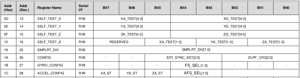
The first two columns of the register map represent the address in HEX and decimal formats followed by the register name. Some of the registers are read-only (marked with R) and others allow us to write (marked with R/W). The content of the register is represented using 8-bits. In various cases, register's value may represent more than one thing, in other words, every bit or group of bits may have a different meaning, e.g., CONFIG (register 26).
The MPU-6050 has 16-bits precision for each of the sensors. That means that two 8-bits registers are used to represent the output. We will read 8-bits data separately from each register and then concatenate them to form 16-bits.
Install Arduino library for I2C
We will use I2C protocol to interact with registers and read/write data. The I2C library provides a very simple interface for that purpose and can be reused in other projects that use I2C protocol. It can be downloaded from our official repository.
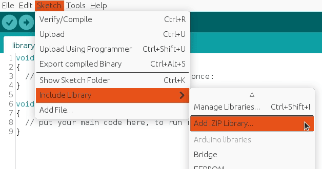
To import a library, open the Arduino IDE, go to Sketch > Include Library > Add .ZIP Library and select the library file downloaded from our GitHub repository.
Then you can simply use include statement:
#include "I2C.h"
It will include the library with predefined functions to interact with registers.
Arduino code
We've defined a separate struct for each raw sensor data: gyroscope_raw, accelerometer_raw and temperature_raw. Every raw struct has a data normalizer function based on the current configuration. Human readable normalized values are stored in another struct called normalized.
Make sure to follow the previous step and import I2C library in order to use it with the include statement:
#include "Wire.h"
#include "I2C.h"

#define MPU6050_IMU_ADDRESS 0x68

#define GYRO_FULL_SCALE_250_DPS  0x00
#define GYRO_FULL_SCALE_500_DPS  0x08
#define GYRO_FULL_SCALE_1000_DPS 0x10
#define GYRO_FULL_SCALE_2000_DPS 0x18

#define ACC_FULL_SCALE_2G  0x00
#define ACC_FULL_SCALE_4G  0x08
#define ACC_FULL_SCALE_8G  0x10
#define ACC_FULL_SCALE_16G 0x18

#define TEMPERATURE_OFFSET 21 // As defined in documentation

#define INTERVAL_MS_PRINT 1000

#define G 9.80665

struct gyroscope_raw {
  int16_t x, y, z;
} gyroscope;

struct accelerometer_raw {
  int16_t x, y, z;
} accelerometer;

struct temperature_raw {
  int16_t value;
} temperature;

struct {
  struct {
    float x, y, z;
  } accelerometer, gyroscope;

  float temperature;
} normalized;

unsigned long lastPrintMillis = 0;

void setup()
{
  Wire.begin();
  Serial.begin(115200);

  I2CwriteByte(MPU6050_IMU_ADDRESS, 27, GYRO_FULL_SCALE_1000_DPS); // Configure gyroscope range
  I2CwriteByte(MPU6050_IMU_ADDRESS, 28, ACC_FULL_SCALE_2G); // Configure accelerometer range
  I2CwriteByte(MPU6050_IMU_ADDRESS, 56, 0x01); // Enable interrupt pin for raw data
}

void loop()
{
  unsigned long currentMillis = millis();

  if (isImuReady()) {
    readRawImu();

    normalize(gyroscope);
    normalize(accelerometer);
    normalize(temperature);
  }

  if (currentMillis - lastPrintMillis > INTERVAL_MS_PRINT) {
    Serial.print("TEMP:\\t");
    Serial.print(normalized.temperature, 2);
    Serial.print("\\xC2\\xB0"); //Print degree symbol
    Serial.print("C");
    Serial.println();

    Serial.print("GYR (");
    Serial.print("\\xC2\\xB0"); //Print degree symbol
    Serial.print("/s):\\t");
    Serial.print(normalized.gyroscope.x, 3);
    Serial.print("\\t\\t");
    Serial.print(normalized.gyroscope.y, 3);
    Serial.print("\\t\\t");
    Serial.print(normalized.gyroscope.z, 3);
    Serial.println();

    Serial.print("ACC (m/s^2):\\t");
    Serial.print(normalized.accelerometer.x, 3);
    Serial.print("\\t\\t");
    Serial.print(normalized.accelerometer.y, 3);
    Serial.print("\\t\\t");
    Serial.print(normalized.accelerometer.z, 3);
    Serial.println();

    Serial.println();

    lastPrintMillis = currentMillis;
  }
}
Note: the snippet is part of Arduino project located in our GitHub repository with the code separated in different logical files.
Testing
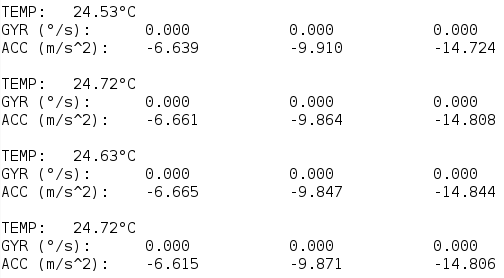
The serial monitor will print last available sensors data every INTERVAL_MS_PRINT milliseconds (in the example above, once per second) and it should be similar to:
Usually the orientation is drawn on the physical module so you can easily detect X, Y and Z axes.
Credits
Official GitHub: https://github.com/hibit-dev/mpu6050


0 Comments