Connecting a motor to Arduino
Arduino microcontrollers are the heart of countless DIY projects, from robots to automated systems. To bring these projects to life, you often need to interface them with motors. In this guide, we'll walk you through the essential steps of connecting a motor to an Arduino using a separate power supply while ensuring control with precision using an NPN transistor. This approach allows you to harness the full potential of your motorized creations without overloading your Arduino.
Components
| 1x Arduino Nano (or another Arduino module)
|
| 1x Mini-breadboard
|
| Dupont wires
|
| NPN Transistor
|
| Resistors kit
|


Prerequisites
We strongly recommend reading our article on transistors to acquire a basic understanding of their functionality and circuit attributes. Additionally, familiarizing yourself with resistors and how to determine their values will be essential for correctly calculating the resistor value for your circuit.
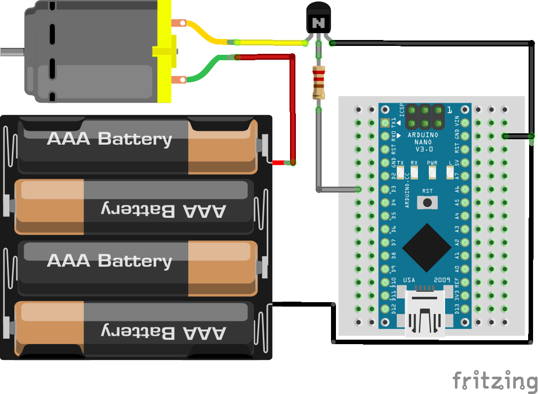
Wiring schema
When working with motors in conjunction with an Arduino, it's crucial to provide a separate power supply for the motor. Motors, especially those with high power requirements, can draw a substantial amount of current that an Arduino alone cannot handle. This separate power source ensures that your Arduino remains undisturbed while the motor operates efficiently.
Connect the positive terminal of the motor's power supply to the motor's positive terminal, the negative terminal of the motor's power supply to the motor's negative terminal, and also connect the ground of the motor's power supply to the Arduino's ground to establish a common ground reference.
To control the motor's operation, an NPN transistor serves as the intermediary between the Arduino and the motor. The base of the NPN transistor connects to an Arduino pin (via a suitable resistor), the collector connects to the motor's positive terminal, and the emitter connects to the Arduino's ground. When you apply a voltage to the base of the transistor, it allows current to flow from the collector to the emitter, thereby turning on the motor.
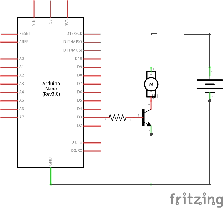
As indicated in the diagram above, there is a resistor positioned between the Arduino D3 pin and the transistor base. In the upcoming section, we will proceed to calculate the value for this resistor.
Calculating base resistor value
In order to compute the base resistor (RB), we must first determine the collector current. Given that the circuit's sole load is the motor, it can be deduced that the collector current is identical to that of the motor. Based on the motor specification, we know that IC = 100 mA, or for practical purposes, IC = 0.1 A. This forms the basis for our calculations.
It is important to note that if we exceed the parameters for which the transistor was designed, it will eventually burn out. With this in mind, we will proceed to identify the transistor's gain from the datasheet. We observe that when IC = 100 mA, its gain is 100. We have now discovered our second value: 𝛽 = 100.
Once we've established the gain, our next step is to calculate the base current. It's important to recognize that the collector current is directly proportional to the base current and the gain. This relationship can be expressed mathematically as:
hFe = 𝛽 (gain) = Ic / Ib
Replacing the values, we acquire our third parameter: Ib = 1mA = 0.001A. Now, we can compute Rb value using Ohm's formula:
Vb = VS - VL = Ib * Rb
Rb = (VS - VL) / Ib
Where VS is the source voltage, and VL is the load voltage. In our circuit, the transistor's base is connected to an output from an Arduino. An Arduino output provides a maximum of 5V and 40mA. Therefore, we have a source voltage of 5V, and the transistor's barrier potential is 0.7V.
Rb = (5V - 0.7V) / 1mA = 4.3kΩ
For our circuit, the appropriate resistor value should be 4.3 kiloohms.
Note that in real-world scenarios, resistors with that specific value aren't available for purchase. Manufacturers predefine the values of commercially available resistors. In simpler terms, resistors are sold in standardized values. We would choose the nearest standardized resistor value which is 4.7 kiloohms.
Arduino code
In this code snippet, we begin by configuring Arduino pin 3 as an output to control the motor. Subsequently, we alternate between turning the motor on and off every three seconds.
#define MOTOR_PIN 3

void setup()
{
  pinMode(MOTOR_PIN, OUTPUT);

  Serial.begin(115200);
}

void loop()
{
  Serial.println("Turning motor ON");
  digitalWrite(MOTOR_PIN, HIGH);
  delay(3000); // Wait three seconds

  Serial.println("Turning motor OFF");
  digitalWrite(MOTOR_PIN, LOW);
  delay(3000); // Wait three seconds
}
We can see that the motor behaved as expected by turning on during three seconds and then turning off.
Conclusion
Incorporating motors into your Arduino projects opens up a world of possibilities, from automated systems to robotics. By providing a separate power supply for the motor and using an NPN transistor for control, you can ensure the safe and efficient operation of your motor while safeguarding your Arduino from excessive current draw. This fundamental approach allows you to unleash the full potential of your projects, making them not only creative but also functional and reliable. So, whether you're building a remote-controlled car or a home automation system, remember these principles to bring your ideas to life with Arduino and motors.
Credits
Official GitHub: https://github.com/hibit-dev/arduino-motor


0 Comments