How to control mini water pump with Arduino
The advent of Arduino microcontrollers has revolutionized the world of electronics and automation. With their user-friendly interface and vast array of modules and sensors, Arduino boards have become the go-to choice for hobbyists and professionals alike. In this article, we will explore the significance of a 5V water pump module, the importance of using transistors, and how to effectively connect the two to create an efficient water control system.
Components
| 1x Arduino Nano (or another Arduino module) |
| 1x Mini-breadboard |
| Dupont wires |
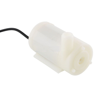
| Water pump |
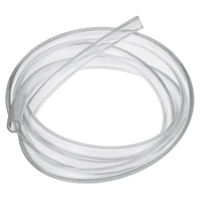
| Water pump pipes |
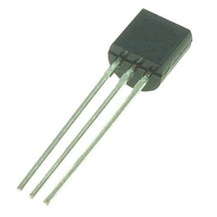
| Transistor |
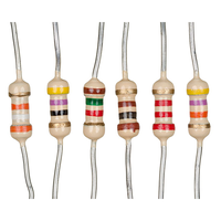
| Resistors kit |


Prerequisites
We really recommend giving our transistor article a look. It'll help you get the hang of how they work and what they do in circuits. Also, it's a good idea to get comfy with resistors and how to figure out what values you need. This knowledge is key to getting the right resistor value for your circuit.
Wiring schema
When working with water pumps in tandem with an Arduino, it's essential to set up a separate power source for the water pump. Pumps, especially those with high power requirements, can draw a substantial amount of current that an Arduino on its own can't handle. This independent power supply ensures that your Arduino can operate without disruption while the pump functions efficiently.
Connect the positive terminal of the pump's power supply to the positive terminal of the pump, and connect the negative terminal of the pump's power supply to the pump's negative terminal. Also, establish a common ground reference by connecting the power supply's ground to the Arduino's ground.
To control the pump's operation, use an NPN transistor as an intermediary between the Arduino and the water pump. Link the base of the NPN transistor to an Arduino pin, utilizing an appropriate resistor. Connect the collector to the pump's positive terminal and the emitter to the Arduino's ground. Applying a voltage to the transistor's base allows current to flow from the collector to the emitter, activating the pump.
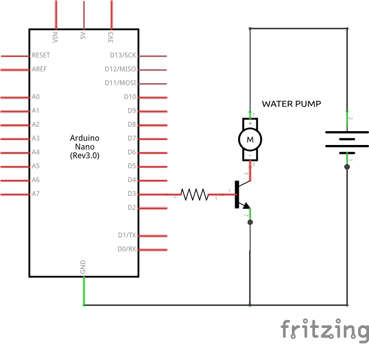
As indicated in the diagram above, there is a resistor positioned between the Arduino D3 pin and the transistor base. In the upcoming section, we will proceed to calculate the value for this resistor.
Calculating base resistor value
In order to compute the base resistor (RB), we must first determine the collector current. Given that the circuit's sole load is the water pump, it can be deduced that the collector current is identical to that of the water pump. Based on the water pump specification, we know that IC = 100 mA, or for practical purposes, IC = 0.1 A. This forms the basis for our calculations.
It is important to note that if we exceed the parameters for which the transistor was designed, it will eventually burn out. With this in mind, we will proceed to identify the transistor's gain from the datasheet. We observe that when IC = 100 mA, its gain is 100. We have now discovered our second value: 𝛽 = 100.
Once we've established the gain, our next step is to calculate the base current. It's important to recognize that the collector current is directly proportional to the base current and the gain. This relationship can be expressed mathematically as:
hFe = 𝛽 (gain) = Ic / Ib
Replacing the values, we acquire our third parameter: Ib = 1mA = 0.001A. Now, we can compute Rb value using Ohm's formula:
Vb = VS - VBE = Ib * Rb
Rb = (VS - VBE) / Ib
Where VS is the source voltage, and VBE is the voltage drop across the base-emitter junction of the transistor. In our circuit, the transistor's base is connected to an output from an Arduino. An Arduino output provides a maximum of 5V and 40mA. Therefore, we have a source voltage of 5V, and the transistor's barrier potential is 0.7V.
Rb = (5V - 0.7V) / 1mA = 4.3kΩ
For our circuit, the suitable value for the base resistor should be equal or below 4.3K ohms. We choose the lower standardized resistor and check by looking at the datasheet curves that the base voltage is sufficient to drive the transistor into saturation. Another way to ensure transistor saturation is to slightly increase the base current. In the example, Arduino may provide up to 40mA to the transistor, so we have room to slightly increase the current.
In the context of designing a transistor circuit, this formula is often employed to determine the necessary base current for attaining a specific collector current with a given gain. It's important to note, however, that the guideline suggesting a base current in the range of 5% to 10% is a practical rule of thumb and doesn't have a direct derivation from this formula.
Note that in real-world scenarios, resistors with that specific value aren't available for purchase. Manufacturers predefine the values of commercially available resistors. In simpler terms, resistors are sold in standardized values. We would choose the nearest standardized resistor value.
Arduino code
In this code snippet, we begin by configuring Arduino pin 3 as an output to control the motor. Subsequently, we alternate between turning the motor on and off every three seconds.
#define PUMP_PIN 13

void setup()
{
  pinMode(PUMP_PIN, OUTPUT);

  Serial.begin(115200);
}

void loop()
{
  Serial.println("Turning pump ON");
  digitalWrite(PUMP_PIN, HIGH);
  delay(3000); // Wait three seconds

  Serial.println("Turning pump OFF");
  digitalWrite(PUMP_PIN, LOW);
  delay(3000); // Wait three seconds
}
We can see that the motor behaved as expected by turning on during three seconds and then turning off.
Conclusion
The 5V water pump module opens up a world of possibilities for automated water control systems, enabling enthusiasts to bring their innovative ideas to life. By employing transistors to interface the water pump with an Arduino, users can ensure the microcontroller's safety and efficiency while managing higher voltage and current requirements.
Credits
Official GitHub: https://github.com/hibit-dev/water-pump

0 Comments