DIY - Automated plants watering system
In the world of do-it-yourself (DIY) projects, few activities match the practicality of constructing your own Arduino-powered automatic watering system. Imagine a setup where technology integrates effortlessly with nature, allowing you to take control of your plant care routine. We'll break down the fundamental components of this project, highlighting the vital role of the DS1302 timekeeping module and Arduino-compatible pumps. Get ready for a hands-on approach that not only enhances your technical skills but also transforms the way you care for your plants, whether they are in the corners of your home or under the open sky.
Automated plants watering project
DIY - Automated plants watering system: concept
DIY - Automated plants watering system: mounting
DIY - Automated plants watering system: code
DIY - Automated plants watering system
Components
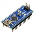
| 1x Arduino Nano (or another Arduino module)
|
| 1x Mini-breadboard
|
| 1x DS1302 module
|
| 1x CR2032 Battery
|
| 1x Water pump
|
| 1x Water pump pipe
|
| 1x Voltage regulator with 5V output (AMS1117)
|
| 1x Switch button $3.34 |
| 1x Push button
|
| 1x Potentiometer
|
| PN2222A Transistor
|
| Resistors kit
|
| 2x LEDs
|
| 2x LED Holder Bezel
|
| 1x Barrel plug
|
| 9V Battery holder + 9V Battery
|


Prerequisites
We suggest reviewing articles that are either directly or indirectly referenced in this guide. This will provide you with a comprehensive understanding of each component and how they interact.
Water deposit
For our watering system, we will need a water container. Any common and standard items suitable for water storage can be used as a deposit. The larger the storage container, the less frequent the need for recharging.
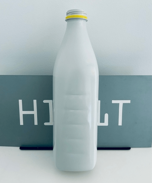
We've selected the bottle shown on the image as our water reservoir. With a capacity of 1.5 liters, it should be sufficient for watering a medium-sized plant for several days.
For the water pump to effectively move water from the bottom of the bottle to the plant, it must be placed inside. To accomplish this, we place the pump inside the bottle, and then we pull out the wires. This involves creating a small opening at the base of the bottle solely for the wires, enabling us to thread them out and connect the pump to our plant care station. To conclude the process, we use waterproof silicone to seal the opening, ensuring there is no water loss.
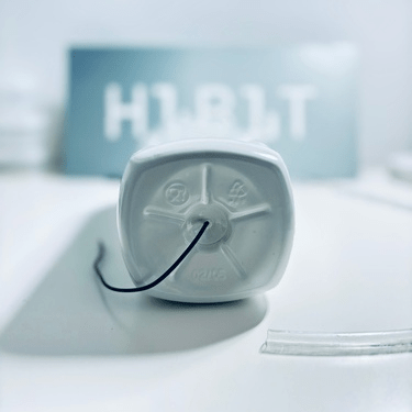
On the opposite end, there will be a water pipe directly connecting to the plant to provide hydration.
Water pump wiring
To facilitate the connection of the pump wires with the main system, we've used a barrel plug. The junction between the pump wires and the connector wires is shielded by heat shrink wraps, providing effective insulation from external elements.
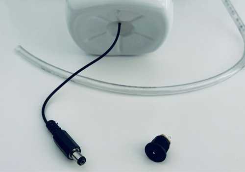
This approach ensures a secure and well-insulated connection, contributing to the overall reliability of the system.
Plants care station
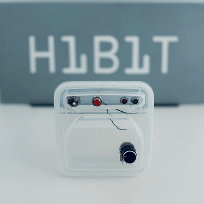
The plants care station takes on the responsibility of processing available information, making decisions, and controlling the activation and deactivation of the watering system. Designed for both indoor and outdoor use, it hides all wiring and functions as a discreet black box. This is achieved by enclosing all system components within the box illustrated below.
The box is easily accessible, facilitating the replacement of components or even reprogramming of the system when necessary. Within the plants care station, the central orchestrator is the Arduino Nano, functioning as the main brain to coordinate all other components. Accompanying this, a DS1302 module is integrated to manage real-time control, influencing watering decisions. It considers optimal watering times, favoring mornings and evenings when sunlight is less intense, promoting better absorption and utilization of water by the plants. This thoughtful scheduling enhances the overall efficiency and well-being of the plants.
Power supply
For the entire system, a 9V battery serves as the power supply. It separately powers both the Arduino and the water pump. Considering that our water pump operates on 5V, we require a voltage transformer. For this purpose, we have used the AMS117 module.
In contrast, the DS1302 operates on a separate CR2032 battery, ensuring a dedicated power source to sustain the Real-Time Clock (RTC) functionality. This dual-power configuration enhances the efficiency and autonomy of each component, ensuring the overall reliability of the system.
Control elements
The plants care station comes equipped with some handy controls like LEDs, buttons, and a potentiometer to enhance its overall functionality. A straightforward on/off switch simplifies the activation of the station. When manual watering is needed, a dedicated push button is readily available. Additionally, the potentiometer allows for accurate adjustment of the water amount during automatic mode.
These user-friendly controls provide a precise and efficient means of managing your plant care routine.
Wiring schema
Creating a precise wiring schema is essential for the optimal performance of the automatic watering system. This schema serves as a practical guide, interconnecting main components. Methodically organizing and routing the wires prevents potential confusion during the assembly process. Clarity in both assembly and troubleshooting phases is achieved through the implementation of color-coded distinctions and strictly following specified pin configurations for facilitating the communication between modules.
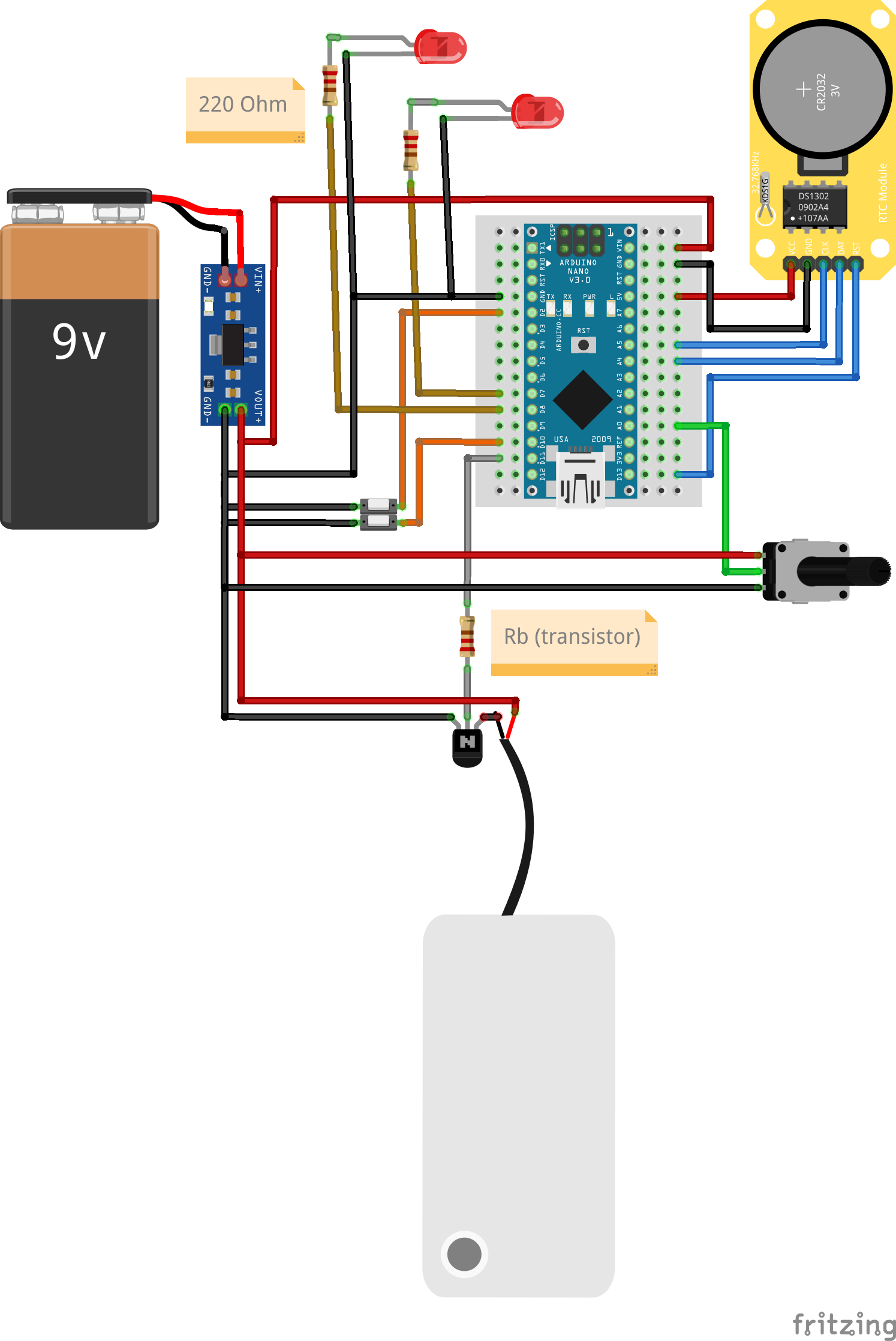
The above wiring schema offers a comprehensive overview of the system wiring and connections.
Calculating base resistor value
In order to compute the base resistor (RB), we must first determine the collector current. Given that the circuit's sole load is the water pump, it can be deduced that the collector current is identical to that of the water pump. Based on the water pump specification, we know that IC = 200 mA, or for practical purposes, IC = 0.2 A. This forms the basis for our calculations.
It is important to note that if we exceed the parameters for which the transistor was designed, it will eventually burn out. With this in mind, we will proceed to identify the transistor's gain from the datasheet. We observe that when IC = 200 mA, its gain is 100. We have now discovered our second value: 𝛽 = 100.
Once we've established the gain, our next step is to calculate the base current. It's important to recognize that the collector current is directly proportional to the base current and the gain. This relationship can be expressed mathematically as:
hFe = 𝛽 (gain) = Ic / Ib
Replacing the values, we acquire our third parameter: Ib = 2mA = 0.002A. Now, we can compute Rb value using Ohm's formula:
Vb = VS - VBE = Ib * Rb
Rb = (VS - VBE) / Ib
Where VS is the source voltage, and VBE is the voltage drop across the base-emitter junction of the transistor. In our circuit, the transistor's base is connected to an output from an Arduino. An Arduino output provides a maximum of 5V and 40mA. Therefore, we have a source voltage of 5V, and the transistor's barrier potential is 0.6V.
Rb = (5V - 0.6V) / 2mA = 2.2kΩ
For our circuit, the suitable value for the base resistor should be equal or below 2.2K ohms. We choose the lower standardized resistor and check by looking at the datasheet curves that the base voltage is sufficient to drive the transistor into saturation.
Automated plants watering system
After going through rounds of mounting and wiring adjustments, we're excited to introduce our initial prototype of the automatic watering system. Check out the results and get a general overview of the system in the attached image below. We're really looking forward to seeing how well it takes care of the plants and are ready to make it even better by identifying areas for improvement.
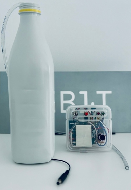
The internal components of the plant care station neatly fit into the box, presenting a clean and user-friendly appearance. The next step involves experimenting and testing the system over some time to identify any weaknesses and enhance its performance. Additionally, we aim to minimize its size and simplify the wiring, making maintenance more straightforward.
Having outlined the concept of automated watering and successfully assembled the physical components, our attention now turns to the real wizardry - the code. This article explores the intricate lines of Arduino code that transform theory into reality, breathing life into our DIY plant care project. As we step into the heart of our automated watering system, let's unravel the details that make our green vision a reality.
Install library for DS1302
To interact with the DS1302 sensor, we will use an existing library. This library, provides an interface that facilitates communication with the module, saving you significant time and providing a reliable and extensively tested code base. It can be downloaded from our official repository.
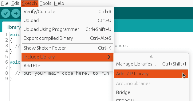
To import a library, open the Arduino IDE, go to Sketch > Include Library > Add .ZIP Library and select the library file downloaded from our GitHub repository.
Then you can simply use include statement:
#include "virtuabotixRTC.h"
It will include the library with predefined functions to interact with the module.
Arduino code
This Arduino code forms the backbone of our automated watering system, translating the idea of plant watering into a functional reality. At its core, this code interfaces with a real-time clock, ensuring our system is attuned to the rhythm of the day. Constants define the timeframes for morning and evening watering sessions, while designated pins for LEDs, buttons, and a potentiometer facilitate the communication among physical components.
In the setup phase, the code initializes pins and stages a brief, illuminating sequence with LEDs, symbolizing the system's awakening. As the main loop takes the stage, it constantly monitors the real-time clock and user inputs. The code continuously checks the time and conditions to trigger morning and evening watering cycles, while also providing a manual watering option through the push button. The iteration transpires every 5 seconds, ensuring a vigilant and responsive approach to the needs of plant care.s.
#include "virtuabotixRTC.h"

#define MORNING_WATERING false
#define EVENING_WATERING true

#define MORNING_WATERING_HOUR 8
#define EVENING_WATERING_HOUR 20

#define LED_RED_PIN 7
#define LED_GREEN_PIN 8

#define BUTTON_PUSH_PIN 10
#define BUTTON_TOGGLE_PIN 2

#define POTENTIOMETER_PIN A0
#define POTENTIOMETER_MIN_SECONDS 0
#define POTENTIOMETER_MAX_SECONDS 10

#define PUMP_BASE_PIN 11

#define DS1302_CLK_PIN A5
#define DS1302_DAT_PIN A4
#define DS1302_RST_PIN 13

bool morningWatered = false;
bool eveningWatered = false;

struct button {
  byte pressed = 0;
};

struct toggle {
  byte on = 0;
};

struct potentiometer {
  byte level = 0;
};

button button;
toggle toggle;

potentiometer potentiometer;

virtuabotixRTC RTC(DS1302_CLK_PIN, DS1302_DAT_PIN, DS1302_RST_PIN);

void setup()
{
  // Set pin mode for LEDs
  pinMode(LED_RED_PIN, OUTPUT);
  pinMode(LED_GREEN_PIN, OUTPUT);

  // Turn red LED ON (setup in progress...)
  digitalWrite(LED_RED_PIN, HIGH);

  delay(3000);

  // Set pin mode for buttons
  pinMode(BUTTON_TOGGLE_PIN, INPUT_PULLUP);
  pinMode(BUTTON_PUSH_PIN, INPUT_PULLUP);

  // Set pin mode for potentiometer
  pinMode(POTENTIOMETER_PIN, INPUT);

  // Set pin mode for water pump
  pinMode(PUMP_BASE_PIN, OUTPUT);

  // Set sketch compiling time
  setDateTime(RTC, __DATE__, __TIME__);

  // Turn red LED OFF and green LED ON
  digitalWrite(LED_RED_PIN, LOW);
  digitalWrite(LED_GREEN_PIN, HIGH);

  delay(1500);

  // Turn green LED OFF
  digitalWrite(LED_GREEN_PIN, LOW);
}

void loop()
{
  // Allow updates of variables
  RTC.updateTime();

  // Read input values
  button.pressed = isButtonPressed(BUTTON_PUSH_PIN);
  potentiometer.level = readPotentiometerLevelMapped(POTENTIOMETER_PIN);
  toggle.on = isToggleOn(BUTTON_TOGGLE_PIN);

  // Turn ON morning watering
  if (MORNING_WATERING && RTC.hours == MORNING_WATERING_HOUR) {
    if (morningWatered == false) {
      morningWatered = true;

      int wateringMilliseconds = getMillisecondsByPotentiometerLevel(potentiometer.level);

      turnPumpTemporaryOn(wateringMilliseconds);
    }
  } else {
    morningWatered = false;
  }

  // Turn ON evening watering
  if (EVENING_WATERING && RTC.hours == EVENING_WATERING_HOUR) {
    if (eveningWatered == false) {
      eveningWatered = true;

      int wateringMilliseconds = getMillisecondsByPotentiometerLevel(potentiometer.level);

      turnPumpTemporaryOn(wateringMilliseconds);
    }
  } else {
    eveningWatered = false;
  }

  // Turn ON manual watering
  if (button.pressed) {
    turnPumpOn();

    // Wait while the button is ON
    do {
      button.pressed = isButtonPressed(BUTTON_PUSH_PIN);

      delay(100);
    } while (button.pressed);

    turnPumpOff();
  }

  delay(5000); // Iterate every 5 seconds
}
Note that the push button triggers manual watering when pressed, adding a layer of user interactivity. Due to the 5000ms delay in the loop function, there might be a delay between pressing the button and the corresponding action. Nevertheless, when the process initiates, the green LED will illuminate.
The potentiometer values manage the water supply to the plant. The code calculates the pump's operational time based on the potentiometer's position. To ensure control and efficiency, we've established limits, where the minimum potentiometer value corresponds to a pump duration of 0 seconds, and the maximum allows up to 10 seconds. These settings remain easily customizable through designated constants.
It's worth mentioning that we've opted to disable the morning watering for our plant, choosing to automate the process exclusively in the evenings. Additionally, while the switch button currently lacks a specific assignment, it stands ready for future functionalities.
The presented Arduino code serves as the operational heart of our automated watering system, consistently monitoring real-time data and user inputs. Its key role is to activate morning and evening watering cycles, currently programmed for 8 in the morning and 20 in the evening, with customizable constants. The iterative loop ensures the system remains alert and responsive to the unique needs of plant care. The entire code is highly customizable through constants, enabling effortless adjustments to the configuration of the plant care station's operation.
Please be aware that the provided code snippet includes only the main segment. The auxiliary functions and definitions can be found in our official GitHub repository.
Conclusion
In the spirit of self-made solutions, this project encourages to approach the process of building, learning, and adapting. The DS1302 timekeeping module and Arduino-compatible pumps play crucial roles in this process, with each component contributing to the synergy between technology and the natural world. The true essence of this project lies not just in the finished product but in the transformative experience of crafting a technological solution for the well-being of your plants, wherever they may be.
In wrapping up our journey through the practical implementation of an Arduino-powered automatic watering system, you've navigated the intricacies of physical mounting, sensor integration, and module connections. What started as abstract concepts has materialized into a self-built, technology-infused plant care solution.
Credits
Official GitHub: https://github.com/hibit-dev/plants-care


0 Comments