DIY - Universal RC Joystick: code
The physical part of the controller is finished but what about the brain? Once more, our decision falls on Arduino Nano. It perfectly fits by size providing all the necessary functionality. For programming a Nano board we need a USB to serial interface which can be hooked up to the programing header located on the top side of our controller.
Below you will find all links to the project posts.
AriControl project
DIY - Universal RC Joystick: concept
DIY - Universal RC Joystick: controls
DIY - Universal RC Joystick: mounting
DIY - Universal RC Joystick: code
DIY - Universal RC Joystick: receiver
Installing Arduino libraries
To interact with NRF24L01 module we make use of existing libraries. The library provides an interface to communicate with the module saving us a lot of time. Another advantage is robust code base tested and improved by the community during years. We recommend to make use of the library and avoid implementing everything from scratch.
Interaction with AirControl is simplified too. We have created a library that works for the transmitter as well as the receiver. Both libraries can be downloaded from our official repository:
RF24 official library: Download here
AirControl official library: Download here
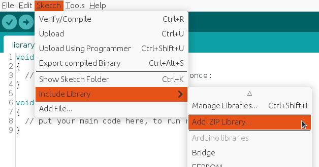
To import a library, open the Arduino IDE, go to Sketch > Include Library > Add .ZIP Library and select the library file downloaded from our GitHub repository.
Then you can simply use include statement:
#include "RF24.h"
#include "nRF24L01.h"
#include "AirControl.h"
AirControl library
AirControl library defines structures for the joystick and control elements available on it. It aggregates small structs that describe each control element and allows to know in every moment the current state of each element.
struct button {
    byte pressed = 0;
};

struct toggle {
    byte on = 0;
};

struct potentiometer {
    byte level = 0;
};

struct analog {
    short x, y;

    button button;
};

//Max size of this struct is 32 bytes - NRF24L01 buffer limit
struct air_control {
    char key[10] = "hibit";

    struct {
      analog left, right;
    } analogs;

    struct {
      toggle upper, lower;
    } toggles;

    struct {
      struct {
        button upper, lower;
      } left, right;
    } buttons;

    struct {
      potentiometer left, right;
    } potentiometers;
};
The library also provides a debug function that outputs the current state of the controller. We will see it later in the testing section.
AirControl Arduino code
Despite the amount of lines, transmitter code is quite simple. It gets together NRF24L01 program and AirControl pins definition for each control element. The readings are saved directly in the AirControl structure defined by the library.
setup() function initiates the NRF24L01 module as transmitter with the provided configuration.
loop() function takes care of updating the payload values and sending them.
#include "SPI.h"
#include "RF24.h"
#include "nRF24L01.h"
#include "AirControl.h"

// NRF24 pins
#define RF24_CE_PIN 9
#define RF24_CSN_PIN 10 //PIN 10 must be output to work as SPI master

// Joystick pins
// Due to physical position of analog modules X and Y axes are inverted
#define ANALOG_LEFT_X_PIN A3
#define ANALOG_LEFT_Y_PIN A4
#define ANALOG_LEFT_BUTTON_PIN A2

#define ANALOG_RIGHT_X_PIN A6
#define ANALOG_RIGHT_Y_PIN A7
#define ANALOG_RIGHT_BUTTON_PIN A5

#define TOGGLE_UPPER_PIN 3
#define TOGGLE_LOWER_PIN 2

#define BUTTON_LEFT_UPPER_PIN 8
#define BUTTON_LEFT_LOWER_PIN 7
#define BUTTON_RIGHT_UPPER_PIN 6
#define BUTTON_RIGHT_LOWER_PIN 5

#define POTENTIOMETER_LEFT_PIN A0
#define POTENTIOMETER_RIGHT_PIN A1

// Default idle values (calibration)
// Due to physical position of analog modules X and Y axes are inverted
#define ANALOG_LEFT_X_CORRECTION 127
#define ANALOG_LEFT_Y_CORRECTION 128

#define ANALOG_RIGHT_X_CORRECTION 126
#define ANALOG_RIGHT_Y_CORRECTION 122

// Debug & security
#define DEBUG false
#define SECURITY_KEY "hibit" // 10 characters max

// Air Control joystick
air_control airControl;

// NRF24L01
RF24 radio(RF24_CE_PIN, RF24_CSN_PIN);

void setup()
{
  pinMode(ANALOG_LEFT_BUTTON_PIN, INPUT_PULLUP);
  pinMode(ANALOG_RIGHT_BUTTON_PIN, INPUT_PULLUP);

  pinMode(TOGGLE_UPPER_PIN, INPUT_PULLUP);
  pinMode(TOGGLE_LOWER_PIN, INPUT_PULLUP);

  pinMode(BUTTON_LEFT_UPPER_PIN, INPUT_PULLUP);
  pinMode(BUTTON_LEFT_LOWER_PIN, INPUT_PULLUP);
  pinMode(BUTTON_RIGHT_UPPER_PIN, INPUT_PULLUP);
  pinMode(BUTTON_RIGHT_LOWER_PIN, INPUT_PULLUP);

  if (DEBUG) {
    Serial.begin(115200);
  }

  const byte address[6] = "00001";

  radio.begin();

  //Append ACK packet from the receiving radio back to the transmitting radio
  radio.setAutoAck(false); //(true|false)
  //Set the transmission datarate
  radio.setDataRate(RF24_250KBPS); //(RF24_250KBPS|RF24_1MBPS|RF24_2MBPS)
  //Greater level = more consumption = longer distance
  radio.setPALevel(RF24_PA_LOW); //(RF24_PA_MIN|RF24_PA_LOW|RF24_PA_HIGH|RF24_PA_MAX)
  //Default value is the maximum 32 bytes
  radio.setPayloadSize(sizeof(air_control));
  //Act as emitter
  radio.openWritingPipe(address);
  radio.stopListening();
}

void loop()
{
  strcpy(airControl.key, SECURITY_KEY); // Skip if not needed. Default value: hibit

  airControl.analogs.left = readAnalog(ANALOG_LEFT_X_PIN, ANALOG_LEFT_Y_PIN, ANALOG_LEFT_BUTTON_PIN, ANALOG_LEFT_X_CORRECTION, ANALOG_LEFT_Y_CORRECTION);
  airControl.analogs.right = readAnalog(ANALOG_RIGHT_X_PIN, ANALOG_RIGHT_Y_PIN, ANALOG_RIGHT_BUTTON_PIN, ANALOG_RIGHT_X_CORRECTION, ANALOG_RIGHT_Y_CORRECTION);

  airControl.toggles.upper = readToggle(TOGGLE_UPPER_PIN);
  airControl.toggles.lower = readToggle(TOGGLE_LOWER_PIN);

  airControl.buttons.left.upper = readButton(BUTTON_LEFT_UPPER_PIN);
  airControl.buttons.left.lower = readButton(BUTTON_LEFT_LOWER_PIN);
  airControl.buttons.right.upper = readButton(BUTTON_RIGHT_UPPER_PIN);
  airControl.buttons.right.lower = readButton(BUTTON_RIGHT_LOWER_PIN);

  airControl.potentiometers.left = readPotentiometer(POTENTIOMETER_LEFT_PIN);
  airControl.potentiometers.right = readPotentiometer(POTENTIOMETER_RIGHT_PIN);

  radio.write(&airControl, sizeof(air_control));

  if (DEBUG) {
    debug(airControl);
  }
}
Note: the snippet is part of Arduino project located in our GitHub repository with the code separated in different logical files.
Security
As part of communication security we have added a security key, defined in SECURITY_KEY constant. It's attached every time the transmitter generates a payload. On the receiver side there is a key guard to make sure incoming key is valid and avoid executing our code in case it's not.
Testing
Enabling debug constant in the main code will output AirControl status via the serial monitor every 100ms.
#define DEBUG true
The output is a graphical representation of the joystick. Push and switch buttons are represented with 1 (on) and 0 (off). In case of potentiometers and analog joystick axes it will be a number between 0 and 255. Debug function also provides some useful information as set security key and used buffer bytes. Just as reminder, NRF24L01 buffer is limited to 32 bytes.
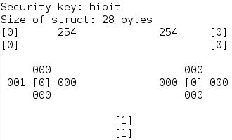
As you can see, buttons state is represented with one digit within brackets and variable values with 3 digits.
Conclusion
Using libraries and predefined structures make things uncomplicated. Prepared debug function provides a clear and real-time output of the state for each control element. Same libraries can be reused on the receiver, helping to debug and verify incoming payload. In the following post, we will cover the receiver part and the code used to run it.
Credits
Official GitHub: https://github.com/hibit-dev/aircontrol
Official nRF24 GitHub: https://github.com/nRF24


0 Comments