DIY - Remote control car running on Arduino
Radio control cars are small vehicles powered by electric or gas motors that can be remotely controlled by a transmitter. The transmitter sends signals to a receiver on the car, allowing the operator to control the car's speed, direction, and steering. Radio control cars are available in a variety of sizes, from miniature models that can fit in the palm of your hand to large off-road vehicles that can climb over rough terrain.
They are often sold with predefined chips and built-in software. Due to limited circuitry and insufficient documentation, enhancing or modifying existing RC cars can become a challenging task. The primary objective of our project is to overcome these obstacles and create a completely customizable RC car that can be fully controlled. In addition, it will be a perfect pair for our AirControl joystick. The name given to the project is Merin.
Merin project
DIY - Remote control car running on Arduino: concept
DIY - Remote control car running on Arduino: mounting
DIY - Remote control car running on Arduino: code
DIY - Remote control car running on Arduino
Prerequisites
Reading the AirControl documentation is highly recommended as it will serve as the car controller. Additionally, we suggest reviewing the L298N motor driver, which will be employed in the project, and familiarizing oneself with buzzers and how they work.
Components
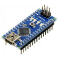
| 1x Arduino Nano (or another Arduino module) $3.39 |
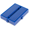
| 1x Mini-breadboard
|
| 1x NRF24L01 (or NRF24L01+ or NRF24L01+PA+LNA) $2.22 |
| 1x NRF24L01 adapter (recommended)
|
| 1x L298N $10.99 |
| 1x Voltage regulator with 5V output (AMS1117) $1.82 |
| 1x Buzzer
|
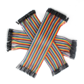
| Dupont wires
|


Frame and components
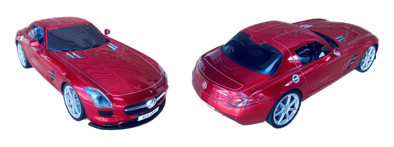
In the context of the project, the decision was made not to create a new RC car from raw materials, but rather to purchase an already existing model. Modifying an existing model would allow us to skip many of the time-consuming steps and focus primarily on the modifications. This will allow us to save time and resources while still achieving the desired outcome. Additionally, acquiring a pre-assembled RC car provides more sophisticated design than the team would have been able to create independently.
Once we had reviewed all the available options, we selected a 1:18 scale car with black windows and a spacious interior (hopefully). We are optimistic that this choice will meet our needs.
The car already includes valuable features that can be reused such as front headlights, brake lights and functional suspension. The project involves using AirControl joystick as primary control mechanism. The original joystick will not work once the modifications are complete. The custom joystick will offer unique features that the original one lacks.
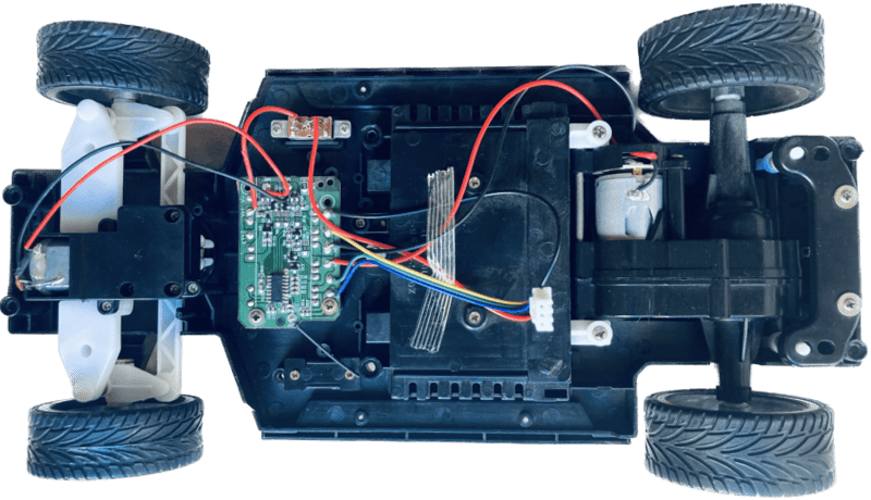
Original state and cleanup
We began our investigation by disassembling the frame to uncover its internal components and understand how they work. By gaining a clear understanding of the car's original configuration, we were able to approach the modifications with greater confidence, knowing what changes were necessary and how they would integrate with the existing system.
After the initial inspection and disassembly, the team was able to identify which components could be repurposed, which ones could be improved, and which ones were not necessary. We also identified areas where we could introduce new features to enhance the car's functionality. To start mounting new components, we first unmounted the existing ones and ensured that we keep the necessary elements. The original state of the car and its internal components can be seen in the image below.
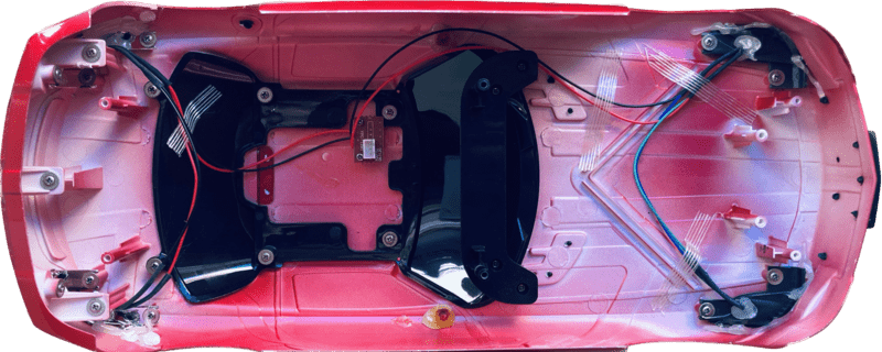
The headlights and brake lights are installed on the top frame, providing a convenient 3-pin connector. Our intention is to keep the wiring and improve their functionality in code.
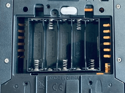
In our prototype, the AA batteries box will be removed and replaced with 9V battery. Given that the L298N module has a 2V voltage drop, we can expect a similar final voltage. For other components, and to provide a stable current, AMS1117 voltage regulator will be added.
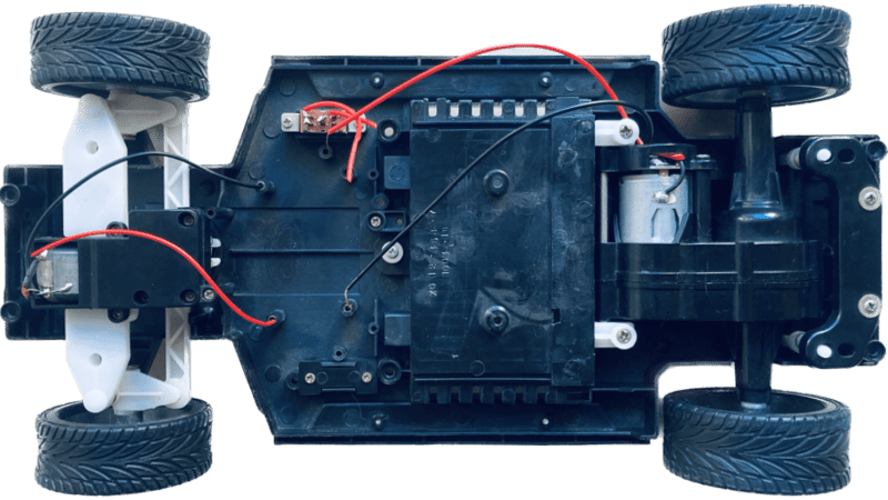
After removing all the unnecessary components from the car, we begin the process of designing and mounting our custom circuitry.
System assembly and integration
The only remaining elements are the suspension, direction, motors, and lights. We aim to not only utilize those existing elements but also enhance their functionality. To control the direction and speed of the motors, we will be using the L298N module. This particular module has the capability to control up to two DC motors at once, allowing for precise and efficient control over the movement of the vehicle. Exactly what we need.
Direction motor
In our initial plans, we aimed to make possible various turning angles for the car. However, evaluating the original direction motor, we realized it wouldn't be adequate for that. Therefore, the car's direction will only have three states: left, right, and none. However, we have expanded the turning range of the vehicle by removing a small plastic section located on the wheels direction.
Speed motor
Initially, the motors could only apply full throttle. Our objective is to enhance this functionality by enabling a variable speed control, which would allow the motors to steadily increase or decrease their velocity, or sustain a constant speed.
While these cars don't come with built-in braking, we can use the motors to slow down and stop the vehicle. We'll do this by reducing the motor speed, either to a lower speed or to zero.
Finally we'll simulate inertia by gradually reducing the speed over time.
Additional features
Our intention was to incorporate the head and brake lights of the car into our design. The original lights were designed to be continuously on and couldn't be turned off. We are going to improve that functionality by enabling the lights to be turned on and off. Furthermore, we aimed to provide independent control of the headlights. On the other side, to ensure that the brake lights are easily distinguishable, we have set the default position lights intensity slightly lower than that of the brake lights.
An added function we are incorporating is a horn that utilizes a buzzer to generate sound. It can be triggered by a dedicated button on the joystick.
Microcontroller
The car's functions, such as the motor controller, lights, and direction control, will be coordinated and controlled by an Arduino Nano, which will serve as the brain and central hub for all of the car's features. Additionally, as the goal is to pair Merin with the AirControl joystick, the Arduino Nano will communicate with the joystick via an NRF24L module. This wireless communication will allow greater flexibility controlling the car, as well as enabling potential future modifications.
Wiring schema
The power source for the remote-controlled car is a 9V battery, which will provide enough power to supply the circuit and both motors for speed and direction control. The buzzer, lights, and NRF24L01 communication module are directly connected to the Arduino Nano. The use of a 9V battery is a good choice as it provides enough voltage to run the system without being too heavy for the vehicle.
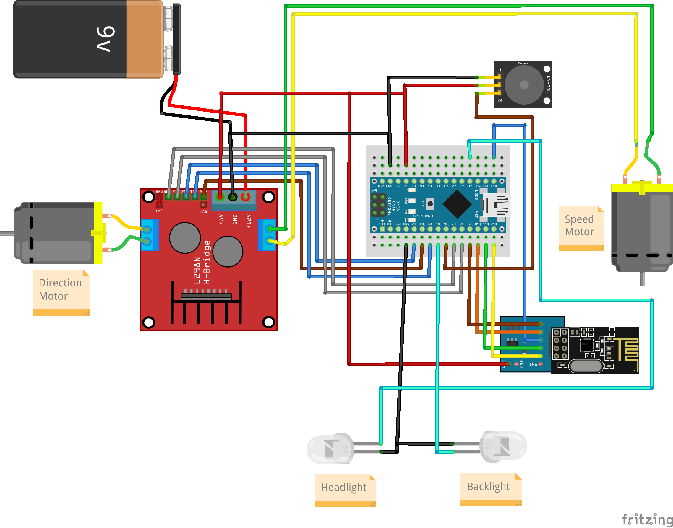
The ENB jumper has been set on the L298N module, which indicates that the direction motor will not support PWM but will only respond to HIGH and LOW signals.
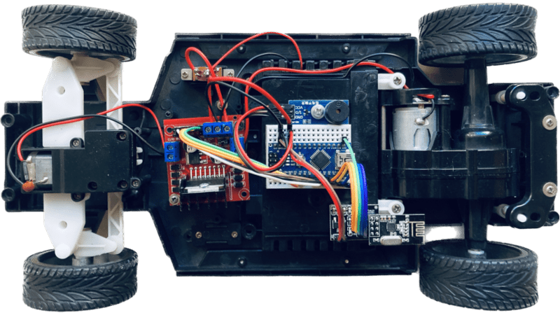
The final circuitry has been carefully mounted onto the frame of the car. This circuitry allows new features to be implemented, including the ability to control the speed of the vehicle, turn on and off the lights, and even honk the horn.
The physical assembly of the car has been completed with all the components properly installed and ready for use. The next steps involve reprogramming the Arduino Nano with the appropriate software to enable all the features, including pairing the car with the AirControl joystick via the NRF24L01 module.
Installing Arduino libraries
Using existing libraries, we can communicate with the NRF24L01 module and save time. These libraries have been tested and improved by the community over the years, providing a robust code base. We strongly suggest using these libraries instead of building everything from scratch. The same applies to the AirControl library that simplifies the usage by providing pre-defined structures.
These libraries can be downloaded from our official repository:
RF24 official library: Download here
AirControl official library: Download here
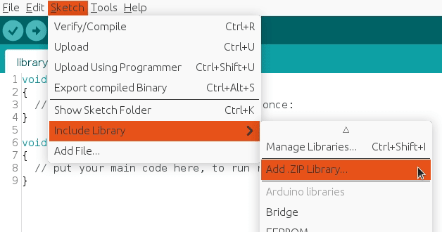
To import a library, open the Arduino IDE, go to Sketch > Include Library > Add .ZIP Library and select the library file downloaded from our GitHub repository.
Then you can simply use include statement:
#include "RF24.h"
#include "nRF24L01.h"
#include "AirControl.h"
AirControl library
The AirControl library defines structures for the joystick and its control elements. These structures contain information about each control element and allow us to know the current state of each element at any given moment.
struct button {
    byte pressed = 0;
};

struct toggle {
    byte on = 0;
};

struct potentiometer {
    byte level = 0;
};

struct analog {
    short x, y;

    button button;
};

//Max size of this struct is 32 bytes - NRF24L01 buffer limit
struct air_control {
    char key[10] = "hibit";

    struct {
      analog left, right;
    } analogs;

    struct {
      toggle upper, lower;
    } toggles;

    struct {
      struct {
        button upper, lower;
      } left, right;
    } buttons;

    struct {
      potentiometer left, right;
    } potentiometers;
};
The library additionally includes a debug function that displays the current state of the controller.
Remote control
The advantage of using custom components and the AirControl joystick is the ability to fully customize the communication. This allows us to assign specific functions to buttons and control various features in the way we prefer.
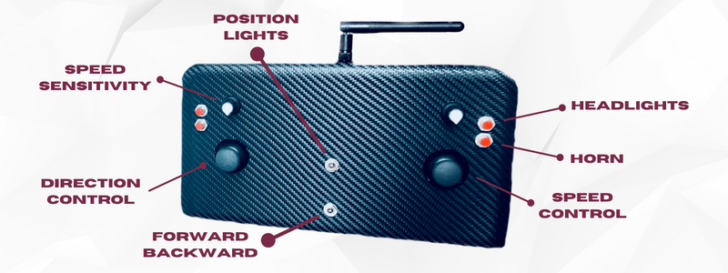
The image displayed above provides a clear overview of how we have mapped the different buttons and components of the AirControl joystick to control various functions of the car. By mapping the different joystick components to specific functions, we are able to have full control over the car's movements and other features. By reading the code in the following section, it will become apparent how each button is utilized.
Merin Arduino code
The source code for the Merin project is organized into separate logical files with descriptive names, each responsible for a specific component or a part of it. The main.ino file contains the program's entry point and definitions, while the remote car logic is contained in the merin.ino file. All functions in this file use a common language and are well-documented with comments to clarify certain sections of code.
void control()
{
  bool hasLightsOn = airControl.toggles.upper.on;

  // Driving dark places?
  if (airControl.buttons.right.upper.pressed || hasLightsOn) {
    headlightsOn();
  } else {
    lightsOff();
  }

  // Setting direction
  if (airControl.toggles.lower.on) {
    if (isMotorDirectionUnset(motorSpeed) || isMotorDirectionForward(motorSpeed)) {
      brakelightsOn();
      switchDirectionBackward();
    }
  } else {
    if (isMotorDirectionUnset(motorSpeed) || isMotorDirectionBackward(motorSpeed)) {
      brakelightsOn();
      switchDirectionForward();
    }
  }

  // Turning left or right?
  if (airControl.analogs.left.x > 50) {
    turnRight();
  } else if (airControl.analogs.left.x < -50) {
    turnLeft();
  } else {
    turnNone();
  }

  // Setting speed
  if (airControl.analogs.right.y < -10 ) {
    brakelightsOn();
    brake(airControl.analogs.right.y);
  } else {
    // Recheck lights
    if (hasLightsOn) {
      lightsOn();
    } else {
      brakelightsOff();
    }

    if (airControl.analogs.right.y > 15) {
      accelerate(airControl.analogs.right.y, airControl.potentiometers.left.level);
    } else {
      brakeGradually(random(2));
    }
  }


  // Make some noise!
  if (airControl.buttons.right.lower.pressed) {
    hornOn();
  } else {
    hornOff();
  }

  delay(30);
}

void switchDirectionBackward()
{
  brakeUntilStop();
  setMotorDirectionBackward(motorSpeed);
  sendToSpeedMotor();
}

void switchDirectionForward()
{
  brakeUntilStop();
  setMotorDirectionForward(motorSpeed);
  sendToSpeedMotor();
}

void accelerate(int speed, byte precision)
{
  int speedToApply = map(speed, 0, 127, 0, precision);

  if (speedToApply < motorSpeed.speed) {
    return;
  }

  setMotorSpeed(motorSpeed, speedToApply);
  sendToSpeedMotor();
}

void brake(int speed)
{
  int value = map(speed, 0, -127, 0, motorSpeed.speed);

  setMotorSpeed(motorSpeed, motorSpeed.speed - value);
  sendToSpeedMotor();
}

void brakeGradually(int delta)
{
  int value = max(0, motorSpeed.speed - delta);

  setMotorSpeed(motorSpeed, value > 30 ? value : 0);
  sendToSpeedMotor();
}

void brakeUntilStop()
{
  setMotorSpeed(motorSpeed, 0);
  unsetMotorDirection(motorSpeed);
  sendToSpeedMotor();

  delay(100);
}

void turnNone()
{
  unsetMotorDirection(motorDirection);
  sendToDirectionMotor();
}

void turnLeft()
{
  setMotorDirectionForward(motorDirection);
  sendToDirectionMotor();
}

void turnRight()
{
  setMotorDirectionBackward(motorDirection);
  sendToDirectionMotor();
}
Note: the snippet is part of Arduino project located in our GitHub repository with the code separated in different logical files.
Code explanation
The speed control joystick is used for acceleration with positive values and braking with negative ones. To prevent errors with small values, a threshold has been set to ignore them. The same approach is taken with the direction analog module, but with a higher threshold since there are only two turn states.
The car's speed will increase with higher provided values and gradually decrease to 0 without acceleration. It simulates the effect of inertia instead of abruptly stopping the car. To improve speed control, a sensitivity rate can be set using the right side potentiometer. When the shaft is turned to maximum, the speed control joystick will be in the highest sensitivity mode.
As a quick note, when the car is braking, the corresponding rear red lights turn on. When the position lights are on, the braking lights can still be distinguished as they shine brighter than the regular position lights.
Conclusion
The Arduino Nano acts as the main control unit for the car, allowing us to coordinate and manage all of its functions. This provides us with the flexibility to personalize the car to meet our specific needs with a wide range of features that can be controlled by the AirControl joystick. The modifications we made to the car will not only make it more enjoyable to use but also increase its versatility beyond its original capabilities. We understand that there are various areas for improvement, from the battery to the motors. However, that is beyond the scope of the current post.
Credits
Official GitHub: https://github.com/hibit-dev/merin
Official AirControl GitHub: https://github.com/hibit-dev/aircontrol


0 Comments