circuit


Pressure and temperature measurement with GY-65

  • avatar
  • 4.2K Views
  • 1 Like
  • 5 mins read
Preview image

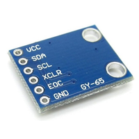
Precision monitoring of atmospheric conditions becomes a reality with the GY-65 module based on BMP085 sensor. Armed with the ability to measure temperature, pressure, and altitude, the GY-65 module opens up a world of possibilities for weather stations, altitude tracking devices, and other projects requiring accurate environmental data. In this article, we delve into the capabilities of the module, examining its features, connectivity with Arduino.

Using touch sensor with Arduino

  • avatar
  • 4.4K Views
  • 4 mins read
Preview image

Touch sensor (also known as touch button) is widely used to control devices. It detects touch, force or pressure on its surface changing the logic state of the circuit. Actually, it works in very similar way as to buttons. Checkout the wiring and Arduino code implementation to track the current state and the state changes.

Using push buttons with Arduino

  • avatar
  • 4.6K Views
  • 2 Likes
  • 4 mins read
Preview image

Today we are going to speak about push buttons, the wiring and how to implement the code for this circuit elements in Arduino. Push buttons connect two points in a circuit when you press them. That means that logic state of the circuit change when you press and keep pressed the button.

 Join Our Monthly Newsletter

Get the latest news and popular articles to your inbox every month

We never send SPAM nor unsolicited emails

How to use tricolor LED module with Arduino

  • avatar
  • 4.2K Views
  • 3 Likes
  • 4 mins read
Preview image

The KY-016 is capable of producing wide range of different colors by mixing blue, green and red lights. The RGB LED module will not require any limiting resistors. Those resistors are already integrated in the circuit, and so 5V can be directly used as power input.

Using switch buttons with Arduino

  • avatar
  • 3.7K Views
  • 3 Likes
  • 4 mins read
Preview image

Let's speak now about switch buttons, the wiring and how to implement the code for this circuit elements in Arduino. Switch buttons connect two points in a circuit when you press them and maintain the state without the need to keep the button pressed. That means that logic state of the circuit change every time you press the button.

Connecting tilt sensor with Arduino

  • avatar
  • 3.3K Views
  • 1 Like
  • 5 mins read
Preview image

A tilt sensor is a type of sensor that can detect the orientation or tilt of an object relative to the force of gravity. It works by measuring the change in angle of the object with respect to the vertical axis.

Tilt sensors can be found in various forms, such as simple mechanical switches, mercury switches, and electronic sensors. They are commonly used in applications that require the detection of tilting or changes in orientation, such as in construction equipment, automotive safety systems, robotics, and gaming controllers.

Simple steps for building circuits with breadboards

  • avatar
  • 2.8K Views
  • 6 mins read
Preview image

A breadboard is an essential tool for working with electronics. It provides a quick and convenient way to test, build, and modify circuits without soldering. Named after the wooden boards originally used to organize components, modern breadboards are plastic boards filled with a grid of tiny holes and internal connectors. This structure lets you easily plug in components and wires, making it ideal for experimenting and prototyping before committing to a permanent setup.

Pull-up and Pull-down resistors

  • avatar
  • 3.8K Views
  • 4 mins read
Preview image

A resistor is a passive two-terminal electrical component that implements electrical resistance as a circuit element. In electronic circuits, resistors are used to reduce current flow and adjust signal levels among other uses. Resistance is measured in Ohm with a sign of Ω.

A microcontroller (e.g. Arduino) utilizes I/O signals for communication with external hardware devices, where the most commonly known being GPIO. As a reminder, digital logic circuits have three logic states: high, low and floating (or high impedance). When there’s nothing connected to your GPIO pins, your program will read a floating impedance state, which we do not want. To achieve either high or low states, we’ll have to implement pull-up or pull-down resistors in our digital circuit.

Regulated power supply module based on AMS1117

  • avatar
  • 2.9K Views
  • 5 Likes
  • 3 mins read
Preview image

We often use the power supplies like batteries or direct AC/DC supply which are normally in higher ranges compared to the actual requirement for the circuit. In that cases we need this kind of voltage regulators which can regulate and vary the voltage levels for the circuit requirement.

The AMS1117 series of chips are linear voltage regulators with low voltage drop. The modules based on the AMS1117 chip provide constant 3.3V or 5V outputs from an unregulated DC input. It's very compact and can be included in your project schema or you can use it together with a breadboard for circuit testing.