DIY - Universal RC Joystick
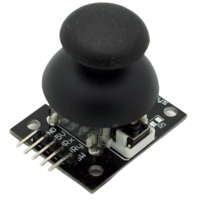
Controlling devices over a distance opens lots of possibilities. Our Arduino roadmap contains many projects that must be controlled remotely and sometimes on a long-distance. Of course, it can be done with a PC but our experience has shown that it becomes complicated when you need long way, portable and rapid communications. Our solution was designing a multi-functional remote controller, we have called it AirControl. Aware of the needs it will have 4 push buttons, 2 switch buttons, 2 potentiometers and two analog modules. Additionally, each analog joystick module has integrated push button.
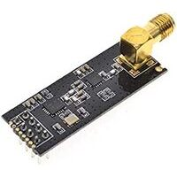
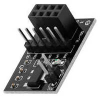
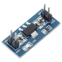
Once more, the microcontroller decision falls on Arduino Nano. It perfectly fits by size providing all the necessary functionality. The responsible of wireless communication will be NRF24L01+PA+LNA module. The range extender chip along with external antenna helps the module achieve about 1000m. The NRF24L01 module strictly needs 3.3V but the logic pins are 5V tolerant. That why we recommend to use the NRF24L01 adapter which acts as regulator, keep the voltage stable, apply filtering and reduce noises.
Below you will find all links to the project detailed posts.
AriControl project
DIY - Universal RC Joystick: concept
DIY - Universal RC Joystick: controls
DIY - Universal RC Joystick: mounting
DIY - Universal RC Joystick: code
DIY - Universal RC Joystick: receiver
DIY - Universal RC Joystick
Components
| 2x Arduino Nano (or another Arduino module) |
| 2x Mini-breadboard |
| 2x NRF24L01 (or NRF24L01+ or NRF24L01+PA+LNA) |
| 2x NRF24L01 adapter |
| 2x Analog joysticks (KY-023) |
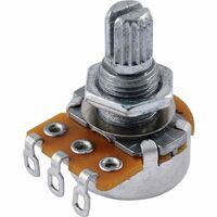
| 2x Potentiometers |
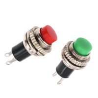
| 4x Push buttons |
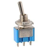
| 2x Switch buttons |
| 1x Voltage regulator with 5V output (AMS1117) |
| 1x PCB board |
| Dupont wires |
| AirControl official library |
| RF24 official library |


Prerequisites
Understanding how communications and each of the control elements work separately:
Forepart
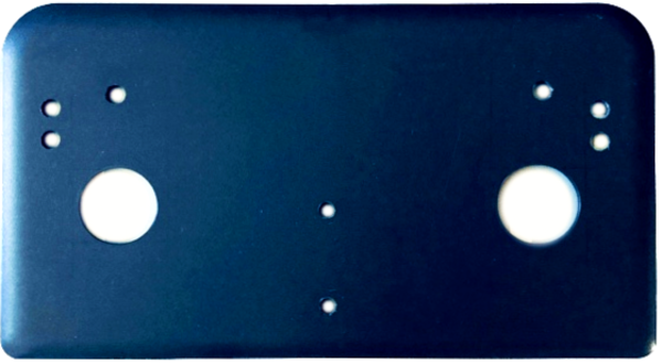
For the front of the joystick we've used the following plastic part. It has appropriate size and shape for our remote controller. This part will contain the set of necessary controls, i.e., buttons, potentiometers, switches and analog joysticks. Therefore, we've perforated the openings for that elements to pass through, according to their dimensions, in the positions we wanted to place them.
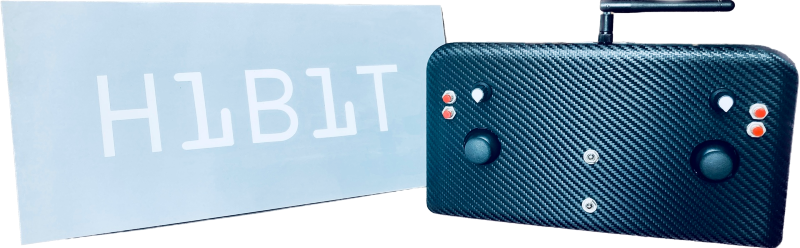
Positions were chosen to make holding comfortable and within the range of the fingers. For a better presentation we've wrapped it with carbon vinyl.
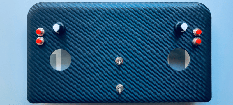
Joystick forepart has the openings for both analog joystick modules. However, the part itself is located on the backside. Take into consideration, as we mentioned before, that each analog module has integrated push button.
To make wiring easier we have soldered one side of dupont wires to the control element leaving the other side with the connector. That way we can directly plug it to a breadboard (using pins) or a pinned module.
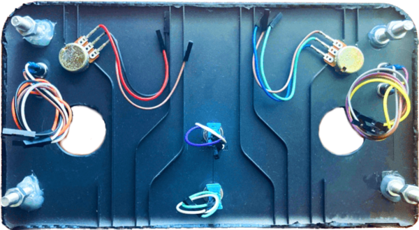
Once finished the forepart we proceed with the backside.
Backside
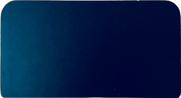
For the joystick backside 4mm black acrylic is used. It was cut from a bigger piece to make sure it has the same shape as the forepart. This will be the base of our joystick and it will assemble the head controller, communication elements, power supply and adapters/regulators.
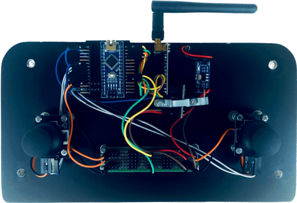
Basically, it gets together all the head components of our joystick. The adapter with NRF24L01+PA+LNA is aligned to center. On one side it has voltage regulator; on the other side mini-breadboard with Arduino Nano. Chosen NRF24L01 module variation, with an amplified antenna, consumes more energy but provides better results for distance.
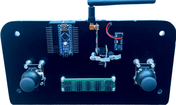
Analog joystick modules are located on this part too. They don't have the proper height so it was adjusted in order to be visible from the cover holes.
Connection hub
As you can see on the image there is a custom PCB board at the bottom. It acts as a connection hub to facilitate connections between different components.
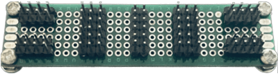
Pins soldering was done with a specific purpose. Top corner pins will connect and act as VCC and bottom corner pins as GND. Pins in the middle are horizontally connected to act as jumpers.
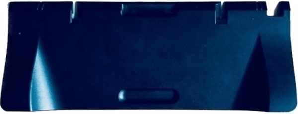
Finally, to better fit in hands and make it more comfortable, the following component is attached to the backside.
Power supply
It's recommended to have a dedicated power supply for each joystick element. We've decided to go forward with 9V battery located within 9V battery holder (as shown on the image below). It will be located on the backside of the joystick, on top of the supporting element. As everything in the joystick circuit will use 5V we need a voltage regulator to convert that 9V to 5V.
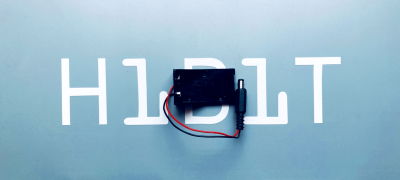
The final version of battery holder has a slight modification. Jack connector is replaced with dupont connectors so we can easily use them with a breadboard or a pinned module.
Wiring schema
Let’s take a look at the circuit diagram. It seams complicated at first sight but it makes total sense when there is a clear understanding on how each component operates as independent unit.
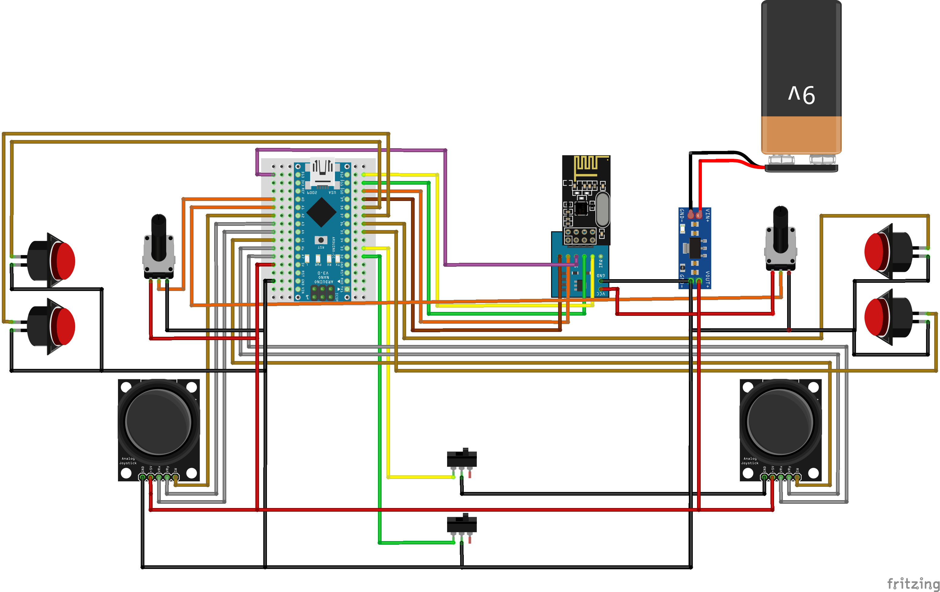
Control elements that need VCC connection use the regulated power from AMS1117. And, all the GND connections finally converge in the same point, going directly to AMS1117 module GND pin.
So, how it looks like in the real life? Take a look.
Available Arduino pins will be used to connect joystick controls according to the circuit diagram: directly or through the connection hub.
Installing Arduino libraries
To interact with NRF24L01 module we make use of existing libraries. The library provides an interface to communicate with the module saving us a lot of time. Another advantage is robust code base tested and improved by the community during years. We recommend to make use of the library and avoid implementing everything from scratch.
Interaction with AirControl is simplified too. We have created a library that works for the transmitter as well as the receiver. Both libraries can be downloaded from our official repository:
RF24 official library: Download here
AirControl official library: Download here
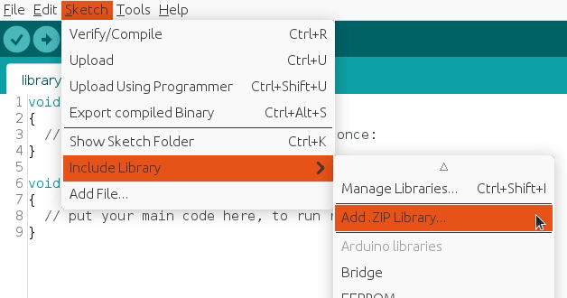
To import a library, open the Arduino IDE, go to Sketch > Include Library > Add .ZIP Library and select the library file downloaded from our GitHub repository.
Then you can simply use include statement:
#include "RF24.h"
#include "nRF24L01.h"
#include "AirControl.h"
AirControl library
AirControl library defines structures for the joystick and control elements available on it. It aggregates small structs that describe each control element and allows to know in every moment the current state of each element.
struct button {
    byte pressed = 0;
};

struct toggle {
    byte on = 0;
};

struct potentiometer {
    byte level = 0;
};

struct analog {
    short x, y;

    button button;
};

//Max size of this struct is 32 bytes - NRF24L01 buffer limit
struct air_control {
    char key[10] = "hibit";

    struct {
      analog left, right;
    } analogs;

    struct {
      toggle upper, lower;
    } toggles;

    struct {
      struct {
        button upper, lower;
      } left, right;
    } buttons;

    struct {
      potentiometer left, right;
    } potentiometers;
};
The library also provides a debug function that outputs the current state of the controller. We will see it later in the testing section.
AirControl Arduino code
Despite the amount of lines, transmitter code is quite simple. It gets together NRF24L01 program and AirControl pins definition for each control element. The readings are saved directly in the AirControl structure defined by the library.
setup() function initiates the NRF24L01 module as transmitter with the provided configuration.
loop() function takes care of updating the payload values and sending them.
#include "SPI.h"
#include "RF24.h"
#include "nRF24L01.h"
#include "AirControl.h"

// NRF24 pins
#define RF24_CE_PIN 9
#define RF24_CSN_PIN 10 //PIN 10 must be output to work as SPI master

// Joystick pins
// Due to physical position of analog modules X and Y axes are inverted
#define ANALOG_LEFT_X_PIN A3
#define ANALOG_LEFT_Y_PIN A4
#define ANALOG_LEFT_BUTTON_PIN A2

#define ANALOG_RIGHT_X_PIN A6
#define ANALOG_RIGHT_Y_PIN A7
#define ANALOG_RIGHT_BUTTON_PIN A5

#define TOGGLE_UPPER_PIN 3
#define TOGGLE_LOWER_PIN 2

#define BUTTON_LEFT_UPPER_PIN 8
#define BUTTON_LEFT_LOWER_PIN 7
#define BUTTON_RIGHT_UPPER_PIN 6
#define BUTTON_RIGHT_LOWER_PIN 5

#define POTENTIOMETER_LEFT_PIN A0
#define POTENTIOMETER_RIGHT_PIN A1

// Default idle values (calibration)
// Due to physical position of analog modules X and Y axes are inverted
#define ANALOG_LEFT_X_CORRECTION 127
#define ANALOG_LEFT_Y_CORRECTION 128

#define ANALOG_RIGHT_X_CORRECTION 126
#define ANALOG_RIGHT_Y_CORRECTION 122

// Debug & security
#define DEBUG false
#define SECURITY_KEY "hibit" // 10 characters max

// Air Control joystick
air_control airControl;

// NRF24L01
RF24 radio(RF24_CE_PIN, RF24_CSN_PIN);

void setup()
{
  pinMode(ANALOG_LEFT_BUTTON_PIN, INPUT_PULLUP);
  pinMode(ANALOG_RIGHT_BUTTON_PIN, INPUT_PULLUP);

  pinMode(TOGGLE_UPPER_PIN, INPUT_PULLUP);
  pinMode(TOGGLE_LOWER_PIN, INPUT_PULLUP);

  pinMode(BUTTON_LEFT_UPPER_PIN, INPUT_PULLUP);
  pinMode(BUTTON_LEFT_LOWER_PIN, INPUT_PULLUP);
  pinMode(BUTTON_RIGHT_UPPER_PIN, INPUT_PULLUP);
  pinMode(BUTTON_RIGHT_LOWER_PIN, INPUT_PULLUP);

  if (DEBUG) {
    Serial.begin(115200);
  }

  const byte address[6] = "00001";

  radio.begin();

  //Append ACK packet from the receiving radio back to the transmitting radio
  radio.setAutoAck(false); //(true|false)
  //Set the transmission datarate
  radio.setDataRate(RF24_250KBPS); //(RF24_250KBPS|RF24_1MBPS|RF24_2MBPS)
  //Greater level = more consumption = longer distance
  radio.setPALevel(RF24_PA_LOW); //(RF24_PA_MIN|RF24_PA_LOW|RF24_PA_HIGH|RF24_PA_MAX)
  //Default value is the maximum 32 bytes
  radio.setPayloadSize(sizeof(air_control));
  //Act as emitter
  radio.openWritingPipe(address);
  radio.stopListening();
}

void loop()
{
  strcpy(airControl.key, SECURITY_KEY); // Skip if not needed. Default value: hibit

  airControl.analogs.left = readAnalog(ANALOG_LEFT_X_PIN, ANALOG_LEFT_Y_PIN, ANALOG_LEFT_BUTTON_PIN, ANALOG_LEFT_X_CORRECTION, ANALOG_LEFT_Y_CORRECTION);
  airControl.analogs.right = readAnalog(ANALOG_RIGHT_X_PIN, ANALOG_RIGHT_Y_PIN, ANALOG_RIGHT_BUTTON_PIN, ANALOG_RIGHT_X_CORRECTION, ANALOG_RIGHT_Y_CORRECTION);

  airControl.toggles.upper = readToggle(TOGGLE_UPPER_PIN);
  airControl.toggles.lower = readToggle(TOGGLE_LOWER_PIN);

  airControl.buttons.left.upper = readButton(BUTTON_LEFT_UPPER_PIN);
  airControl.buttons.left.lower = readButton(BUTTON_LEFT_LOWER_PIN);
  airControl.buttons.right.upper = readButton(BUTTON_RIGHT_UPPER_PIN);
  airControl.buttons.right.lower = readButton(BUTTON_RIGHT_LOWER_PIN);

  airControl.potentiometers.left = readPotentiometer(POTENTIOMETER_LEFT_PIN);
  airControl.potentiometers.right = readPotentiometer(POTENTIOMETER_RIGHT_PIN);

  radio.write(&airControl, sizeof(air_control));

  if (DEBUG) {
    debug(airControl);
  }
}
Note: the snippet is part of Arduino project located in our GitHub repository with the code separated in different logical files.
Security
As part of communication security we have added a security key, defined in SECURITY_KEY constant. It's attached every time the transmitter generates a payload. On the receiver side there is a key guard to make sure incoming key is valid and avoid executing our code in case it's not.
AirControl receiver
Wireless communication implies having a transmitter, in our case the joystick, and a receiver. We must build a simple circuit with NRF24L01 wiring that will act as listener for our joystick. The NRF24L01 module strictly needs 3.3V but the logic pins are 5V tolerant. We recommend to use the NRF24L01 adapter which acts as regulator, keep the voltage stable, apply filtering and reduce noises.
Receiver wiring schema
The NRF24L01 module communicates with the Arduino using SPI protocol. That means that the MOSI, MISO and SCK pins must be connected to their corresponding pins on the microcontroller (another Arduino Nano):
MOSI: Arduino Nano D11
MISO: Arduino Nano D12
SCK: Arduino Nano D13
CE and CSN are connected to Arduino Nano D9 and D10 respectively (other pins can be used)
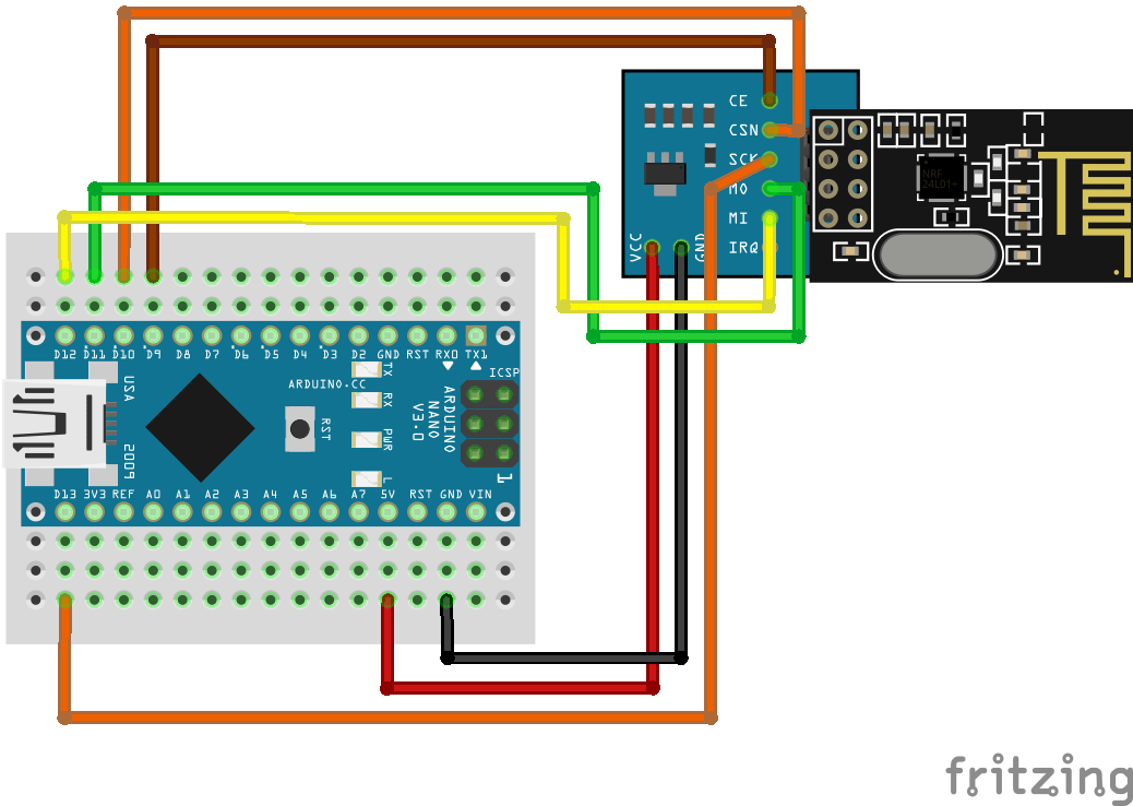
Note: pin D10 is a special pin, it must be set as OUTPUT for the Arduino Nano to operate as a SPI master.
Receiver Arduino code
We will be listening for the AirControl struct and validating incoming signals. The connection will be considered lost after INTERVAL_MS_SIGNAL_LOST milliseconds without incoming message.
setup() function initiates the NRF24L01 module as receiver with the provided configuration.
loop() function takes care of listening for the payload and handling it.
invalidConnection() function handles unknown connections to prevent unwanted behavior.
lostConnection() function handles lost connections to prevent unwanted behavior.
#include "SPI.h"
#include "RF24.h"
#include "nRF24L01.h"
#include "AirControl.h"

// NRF24 pins
#define RF24_CE_PIN 9
#define RF24_CSN_PIN 10 //PIN 10 must be output to work as SPI master

// Time intervals for connection
#define INTERVAL_MS_SIGNAL_LOST 1000
#define INTERVAL_MS_SIGNAL_RETRY 250

// Debug & security
#define DEBUG false
#define SECURITY_KEY "hibit"

// Air Control joystick
air_control airControl;

// NRF24L01
RF24 radio(RF24_CE_PIN, RF24_CSN_PIN);

// Latest signal time
unsigned long lastSignalMillis = 0;

void setup()
{
  if (DEBUG) {
    Serial.begin(115200);
  }

  const byte address[6] = "00001";

  radio.begin();

  //Append ACK packet from the receiving radio back to the transmitting radio
  radio.setAutoAck(false); //(true|false)
  //Set the transmission datarate
  radio.setDataRate(RF24_250KBPS); //(RF24_250KBPS|RF24_1MBPS|RF24_2MBPS)
  //Greater level = more consumption = longer distance
  radio.setPALevel(RF24_PA_LOW); //(RF24_PA_MIN|RF24_PA_LOW|RF24_PA_HIGH|RF24_PA_MAX)
  //Default value is the maximum 32 bytes
  radio.setPayloadSize(sizeof(air_control));
  //Act as receiver
  radio.openReadingPipe(0, address);
  radio.startListening();
}

void loop()
{
  if (radio.available() > 0) {
    radio.read(&airControl, sizeof(air_control));

    if (strcmp(airControl.key, SECURITY_KEY) != 0) {
      invalidConnection(); // Skip if security code is not used
    } else {
      if (DEBUG) {
        debug(airControl);
      }

      // TODO
      // Available values

      // (byte) airControl.analogs.left.x
      // (byte) airControl.analogs.left.y
      // (byte) airControl.analogs.left.button.pressed

      // (byte) airControl.analogs.right.x
      // (byte) airControl.analogs.right.y
      // (byte) airControl.analogs.right.button.pressed

      // (byte) airControl.toggles.upper.on
      // (byte) airControl.toggles.lower.on

      // (byte) airControl.buttons.left.upper.pressed
      // (byte) airControl.buttons.left.lower.pressed
      // (byte) airControl.buttons.right.upper.pressed
      // (byte) airControl.buttons.right.lower.pressed

      // (byte) airControl.potentiometers.left.level
      // (byte) airControl.potentiometers.right.level

      lastSignalMillis = millis();
    }
  }

  if (lastSignalMillis != 0 && millis() - lastSignalMillis > INTERVAL_MS_SIGNAL_LOST) {
    lostConnection();
  }
}

void invalidConnection()
{
  if (DEBUG) {
    Serial.println("Data received but security key is invalid!");

    delay(INTERVAL_MS_SIGNAL_RETRY);
  }
}

void lostConnection()
{
  if (DEBUG) {
    Serial.println("Connection lost, preventing unwanted behavior!");

    delay(INTERVAL_MS_SIGNAL_RETRY);
  }
}
Note: acting against invalid and/or lost signals depends on each project and must be implemented there.
Testing
Enabling debug constant in the main code will output AirControl status via the serial monitor every 100ms.
#define DEBUG true
The output is a graphical representation of the joystick. Push and switch buttons are represented with 1 (on) and 0 (off). In case of potentiometers and analog joystick axes it will be a number between 0 and 255. Debug function also provides some useful information as set security key and used buffer bytes. Just as reminder, NRF24L01 buffer is limited to 32 bytes.
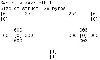
As you can see, buttons state is represented with one digit within brackets and variable values with 3 digits. Debug can be performed on both: on the transmitter sending data and on the receiver reading incoming payload.
Conclusion
Using libraries and predefined structures make things uncomplicated. We clearly reused transmitter's code and avoided writing same things again and again. Prepared debug function provides a real-time output of the state for each control element, that simplifies the verification of the incoming payload.
One of our main goals is having a single point of control to manage different devices with just some small adjustments at the receiver side. Our remote controller has 8 buttons, 2 potentiometers and 2 biaxial joysticks. We actually ended up using almost all analog and digital pins of the Arduino Nano. In case it's needed, the position of Arduino makes easy to connect the USB, debug or reprogram the joystick.
Credits
Official GitHub: https://github.com/hibit-dev/aircontrol
Official nRF24 GitHub: https://github.com/nRF24


0 Comments